- 您現(xiàn)在的位置:買賣IC網(wǎng) > PDF目錄369509 > BT137-700G TRIAC|700V V(DRM)|8A I(T)RMS|TO-220 PDF資料下載
參數(shù)資料
| 型號: | BT137-700G |
| 英文描述: | TRIAC|700V V(DRM)|8A I(T)RMS|TO-220 |
| 中文描述: | 可控硅| 700V的五(DRM)的| 8A條口(T)的有效值|至220 |
| 文件頁數(shù): | 183/224頁 |
| 文件大小: | 2697K |
| 代理商: | BT137-700G |
第1頁第2頁第3頁第4頁第5頁第6頁第7頁第8頁第9頁第10頁第11頁第12頁第13頁第14頁第15頁第16頁第17頁第18頁第19頁第20頁第21頁第22頁第23頁第24頁第25頁第26頁第27頁第28頁第29頁第30頁第31頁第32頁第33頁第34頁第35頁第36頁第37頁第38頁第39頁第40頁第41頁第42頁第43頁第44頁第45頁第46頁第47頁第48頁第49頁第50頁第51頁第52頁第53頁第54頁第55頁第56頁第57頁第58頁第59頁第60頁第61頁第62頁第63頁第64頁第65頁第66頁第67頁第68頁第69頁第70頁第71頁第72頁第73頁第74頁第75頁第76頁第77頁第78頁第79頁第80頁第81頁第82頁第83頁第84頁第85頁第86頁第87頁第88頁第89頁第90頁第91頁第92頁第93頁第94頁第95頁第96頁第97頁第98頁第99頁第100頁第101頁第102頁第103頁第104頁第105頁第106頁第107頁第108頁第109頁第110頁第111頁第112頁第113頁第114頁第115頁第116頁第117頁第118頁第119頁第120頁第121頁第122頁第123頁第124頁第125頁第126頁第127頁第128頁第129頁第130頁第131頁第132頁第133頁第134頁第135頁第136頁第137頁第138頁第139頁第140頁第141頁第142頁第143頁第144頁第145頁第146頁第147頁第148頁第149頁第150頁第151頁第152頁第153頁第154頁第155頁第156頁第157頁第158頁第159頁第160頁第161頁第162頁第163頁第164頁第165頁第166頁第167頁第168頁第169頁第170頁第171頁第172頁第173頁第174頁第175頁第176頁第177頁第178頁第179頁第180頁第181頁第182頁當(dāng)前第183頁第184頁第185頁第186頁第187頁第188頁第189頁第190頁第191頁第192頁第193頁第194頁第195頁第196頁第197頁第198頁第199頁第200頁第201頁第202頁第203頁第204頁第205頁第206頁第207頁第208頁第209頁第210頁第211頁第212頁第213頁第214頁第215頁第216頁第217頁第218頁第219頁第220頁第221頁第222頁第223頁第224頁

Application Notes
AN1008
2002 Teccor Electronics
Thyristor Product Catalog
AN1008 - 5
http://www.teccor.com
+1 972-580-7777
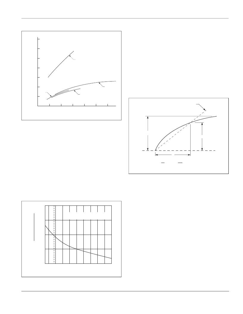
Figure AN1008.9
Typical Triac Latching (I
L
) Requirements for Four
Quadrants versus Gate Current (I
GT
)
I
H
: Holding Current — SCR and Triac
The holding current is the DC principal on-state current below
which the device will not stay in regeneration/on state after latch-
ing and gate signal is removed. This current is equal to or lower
in value than the latching current (Figure AN1008.1 and Figure
AN1008.2) and is related to and has the same temperature
dependence as the DC gate trigger current shown in Figure
AN1008.10. Both minimum and maximum holding current may be
important. If the device is to stay in conduction at low-anode cur-
rents, the maximum holding current of a device for a given circuit
must be considered. The minimum holding current of a device
must be considered if the device is expected to turn off at a low
DC anode current. Note that the low DC principal current condi-
tion is a DC turn-off mode, and that an initial on-state current
(latching current) is required to ensure that the thyristor has been
fully turned on prior to a holding current measurement.
Figure AN1008.10
Normalized DC Holding Current versus
Case Temperature
dv/dt, Static: Critical Rate-of-rise of Off-state Voltage —
SCR and Triac
Static dv/dt is the minimum rate-of-rise of off-state voltage that
a device will hold off, with gate open, without turning on.
Figure AN1008.11 illustrates the exponential definition. This
value will be reduced by a positive gate signal. This charac-
teristic is temperature-dependent and is lowest at the maxi-
mum-rated junction temperature. Therefore, the characteristic
is determined at rated junction temperature and at rated
forward off-state voltage which is also a worst-case situation.
Line or other transients which might be applied to the thyristor
in the off state must be reduced, so that neither the rate-of-
rise nor the peak voltage are above specifications if false firing
is to be prevented. Turn-on as result of dv/dt is non-destructive
as long as the follow current remains within current ratings of
the device being used.
Figure AN1008.11
Exponential Rate-of-rise of Off-state Voltage
Defining dv/dt
dv/dt, Commutating: Critical Rate-of-rise of
Commutation Voltage — Triac
Commutating dv/dt is the rate-of-rise of voltage across the main
terminals that a triac can support (block without switching back
on) when commutating from the on state in one half cycle to the
off state in the opposite half cycle. This parameter is specified at
maximum rated case temperature (equal to T
J
) since it is temper-
ature-dependent. It is also dependent on current (commutating
di/dt) and peak reapplied voltage (line voltage) and is specified at
rated current and voltage. All devices are guaranteed to commu-
tate rated current with a resistive load at 50 Hz to 60 Hz. Com-
mutation of rated current is not guaranteed at higher frequencies,
and no direct relationship can be made with regard to current/
temperature derating for higher-frequency operation. With induc-
tive loading, when the voltage is out of phase with the load cur-
rent, a voltage stress (dv/dt) occurs across the main terminals of
the triac during the zero-current crossing. (Figure AN1008.12) A
snubber (series RC across the triac) should be used with induc-
tive loads to decrease the applied dv/dt to an amount below the
minimum value which the triac can be guaranteed to commutate
off each half cycle.
II
III
IV
I
0
1.0
2.0
3.0
4.0
5.0
6.0
1.0
2.0
3.0
4.0
5.0
6.0
7.0
I
L
I
GT
— mA
0
1.0
2.0
3.0
4.0
-65
-15
+65
+25
+125
-40
Case Temperature (TC) – C
I
H
C
R
I
H
INITIAL ON-STATE CURRENT
= 400 mA dc
Critical dv/dt
dt
V
D
t
t = RC
0
t
63% of V
D
V
D
相關(guān)PDF資料 |
PDF描述 |
|---|---|
| BT137B_SERIES | Triacs |
| BT137B_SERIES_E | Triacs sensitive gate |
| BT137M_SERIES_E | Transient Voltage Suppressor Diodes |
| BT137S_SERIES | Transient Voltage Suppressor Diodes |
| BT137S_SERIES_E | Transient Voltage Suppressor Diodes |
相關(guān)代理商/技術(shù)參數(shù) |
參數(shù)描述 |
|---|---|
| BT137-800 | 功能描述:雙向可控硅 RAIL TRIAC RoHS:否 制造商:STMicroelectronics 開啟狀態(tài) RMS 電流 (It RMS):16 A 不重復(fù)通態(tài)電流:120 A 額定重復(fù)關(guān)閉狀態(tài)電壓 VDRM:600 V 關(guān)閉狀態(tài)漏泄電流(在 VDRM IDRM 下):5 uA 開啟狀態(tài)電壓: 保持電流(Ih 最大值):45 mA 柵觸發(fā)電壓 (Vgt):1.3 V 柵觸發(fā)電流 (Igt):1.75 mA 最大工作溫度: 安裝風(fēng)格:Through Hole 封裝 / 箱體:TO-220AB |
| BT137-800,127 | 功能描述:雙向可控硅 RAIL TRIAC RoHS:否 制造商:STMicroelectronics 開啟狀態(tài) RMS 電流 (It RMS):16 A 不重復(fù)通態(tài)電流:120 A 額定重復(fù)關(guān)閉狀態(tài)電壓 VDRM:600 V 關(guān)閉狀態(tài)漏泄電流(在 VDRM IDRM 下):5 uA 開啟狀態(tài)電壓: 保持電流(Ih 最大值):45 mA 柵觸發(fā)電壓 (Vgt):1.3 V 柵觸發(fā)電流 (Igt):1.75 mA 最大工作溫度: 安裝風(fēng)格:Through Hole 封裝 / 箱體:TO-220AB |
| BT137-800E | 功能描述:雙向可控硅 RAIL TRIAC RoHS:否 制造商:STMicroelectronics 開啟狀態(tài) RMS 電流 (It RMS):16 A 不重復(fù)通態(tài)電流:120 A 額定重復(fù)關(guān)閉狀態(tài)電壓 VDRM:600 V 關(guān)閉狀態(tài)漏泄電流(在 VDRM IDRM 下):5 uA 開啟狀態(tài)電壓: 保持電流(Ih 最大值):45 mA 柵觸發(fā)電壓 (Vgt):1.3 V 柵觸發(fā)電流 (Igt):1.75 mA 最大工作溫度: 安裝風(fēng)格:Through Hole 封裝 / 箱體:TO-220AB |
| BT137-800E,127 | 功能描述:雙向可控硅 RAIL TRIAC RoHS:否 制造商:STMicroelectronics 開啟狀態(tài) RMS 電流 (It RMS):16 A 不重復(fù)通態(tài)電流:120 A 額定重復(fù)關(guān)閉狀態(tài)電壓 VDRM:600 V 關(guān)閉狀態(tài)漏泄電流(在 VDRM IDRM 下):5 uA 開啟狀態(tài)電壓: 保持電流(Ih 最大值):45 mA 柵觸發(fā)電壓 (Vgt):1.3 V 柵觸發(fā)電流 (Igt):1.75 mA 最大工作溫度: 安裝風(fēng)格:Through Hole 封裝 / 箱體:TO-220AB |
| BT137-800E127 | 制造商:NXP 功能描述: 制造商:NXP Semiconductors 功能描述: |
發(fā)布緊急采購,3分鐘左右您將得到回復(fù)。