- 您現(xiàn)在的位置:買(mǎi)賣(mài)IC網(wǎng) > PDF目錄384110 > B500C1500 (Won-Top Electronics Co., Ltd.) 1.5A BRIDGE RECTIFIER PDF資料下載
參數(shù)資料
| 型號(hào): | B500C1500 |
| 廠(chǎng)商: | Won-Top Electronics Co., Ltd. |
| 英文描述: | 1.5A BRIDGE RECTIFIER |
| 中文描述: | 1.5A的橋式整流器 |
| 文件頁(yè)數(shù): | 1/2頁(yè) |
| 文件大?。?/td> | 146K |
| 代理商: | B500C1500 |
B40C1500G THRU B380C1500G
GLASS PASSIVATED SINGLE-PHASE BRIDGE RECTIFIER
Reverse Voltage -
65 to 600 Volts
Forward Current -
1.5 Amperes
FEATURES
Plastic package has Underwriters Laboratory Flammability
Classification 94V-0
Glass passivated chip junctions
High case dielectric strength
Typical I
R
less than 0.1
μ
A
High surge current capability
Ideal for printed circuit boards
High temperature soldering guaranteed:
260°C/10 seconds, 0.375" (9.5mm) lead length,
5 lbs. (2.3kg) tension
MECHANICAL DATA
Case:
Molded plastic body over passivated junctions
Terminals:
Plated leads solderable per MIL-STD-750,
Method 2026
Mounting Position:
Any
Weight:
0.04 ounce, 1.1 grams
MAXIMUM RATINGS AND ELECTRICAL CHARACTERISTICS
Ratings at 25°C ambient temperature unless otherwise specified.
SYMBOLS
B40
C1500G
B80
C1500G
C1500G
B250
C1500G
B380
C1500G
UNITS
Maximum repetitive peak reverse voltage
Maximum RMS input voltage R + C-load
Maximum DC blocking voltage
Maximum peak working voltage
Maximum non-repetitive peak voltage
Maximum repetitive peak forward surge current
Maximum average forward output current for
free air operation at T
A
=45°C R + L-load
V
RRM
V
RMS
V
DC
V
RWM
V
RSM
I
FRM
65
40
65
90
100
125
80
125
180
200
200
125
200
300
350
10.0
400
250
400
600
650
600
380
600
800
1000
Volts
Volts
Volts
Volts
Volts
Amps
I
(AV)
1.6
1.5
Amps
C-load
Peak forward surge current single sine wave on
rated load at T
J
=125°C
Rating for fusing at T
J
=125°C (t<100ms)
Min. series resistor C-load at V
RMS
=
±
10%
Maximum load capacitance +50%
I
FSM
I
2
t
Rt
50.0
12.5
4.0
Amps
A
2
sec
Ohms
1.0
2.0
8.0
12.0
-10%
C
L
5000
2500
1000
500
200
μ
F
Maximum instantaneous forward voltage drop
per leg at 1.5A
Maximum reverse current at rated repetitive
peak voltage per leg T
A
=25°C
Typical thermal resistance
per leg (NOTE 1)
V
F
1.0
Volts
I
R
10.0
36.0
11.0
μ
A
R
Θ
JA
R
Θ
JL
T
J
T
STG
°C/W
Operating junction temperature range
Storage temperature range
-40 to +125
-40 to +150
°C
°C
NOTES:
1. Thermal resistance from junction to ambient and from junction to lead mounted on P.C.B. at 0.375" (9.5mm) lead lengths with 0.2 x 0.2"
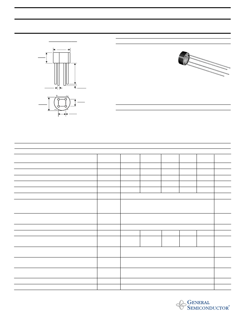
0.220 (5.6)
0.160 (4.1)
0.388 (9.86)
0.348 (8.84)
0.032 (0.81)
0.028 (0.71)
1.0
(25.4)
MIN.
0.060 (1.52)
0.020 (0.51)
0.348 (8.84)
0.308 (7.82)
0.220 (5.6)
0.180 (4.6)
0.220 (5.6)
0.180 (4.6)
Case Style WOG
Dimensions in inches and (millimeters)
4/98
相關(guān)PDF資料 |
PDF描述 |
|---|---|
| B500C2300-1500 | Silicon-Bridge Rectifiers |
| B500C2300-1500A | Silicon-Bridge Rectifiers |
| B500C2300-1500AB | Silicon-Bridge Rectifiers |
| B6014 | BROADBAND ACCESS: xDSL, HPN, CMCs |
| B6105NL | BROADBAND ACCESS: xDSL, HPN, CMCs |
相關(guān)代理商/技術(shù)參數(shù) |
參數(shù)描述 |
|---|---|
| B500C1500 _B0 _10001 | 制造商:PanJit Touch Screens 功能描述: |
| B500C1500A | 制造商:未知廠(chǎng)家 制造商全稱(chēng):未知廠(chǎng)家 功能描述:Replacement with:FSB210/B500C1000A/B500C1500-1000A/B500C2300-1500A |
| B500C1500B | 制造商:未知廠(chǎng)家 制造商全稱(chēng):未知廠(chǎng)家 功能描述:Replacement with:SKB B500C1000 L5B/B500C1000B/B500C1500-1000B/B500C2300-1500B |
| B500C1500G | 制造商:VISHAY 制造商全稱(chēng):Vishay Siliconix 功能描述:GLASS PASSIVATED SINGLE-PHASE BRIDGE RECTIFIER |
| B500C2200 | 制造商:WTE 制造商全稱(chēng):Won-Top Electronics 功能描述:3.7A SINGLE-PHASE BRIDGE RECTIFIER |
發(fā)布緊急采購(gòu),3分鐘左右您將得到回復(fù)。