- 您現(xiàn)在的位置:買賣IC網(wǎng) > PDF目錄375384 > AX88772A (ASIX Electronics Corporation) USB 2.0 to 10/100M Fast Ethernet Controller PDF資料下載
參數(shù)資料
| 型號: | AX88772A |
| 廠商: | ASIX Electronics Corporation |
| 英文描述: | USB 2.0 to 10/100M Fast Ethernet Controller |
| 中文描述: | USB 2.0至個10/100M快速以太網(wǎng)控制器 |
| 文件頁數(shù): | 14/45頁 |
| 文件大小: | 778K |
| 代理商: | AX88772A |
第1頁第2頁第3頁第4頁第5頁第6頁第7頁第8頁第9頁第10頁第11頁第12頁第13頁當(dāng)前第14頁第15頁第16頁第17頁第18頁第19頁第20頁第21頁第22頁第23頁第24頁第25頁第26頁第27頁第28頁第29頁第30頁第31頁第32頁第33頁第34頁第35頁第36頁第37頁第38頁第39頁第40頁第41頁第42頁第43頁第44頁第45頁
ASIX ELECTRONICS CORPORATION
14
AX88772A/AX88172A
Low-pin-count
USB 2.0 to 10/100M Fast Ethernet Controller
2.0 Signal Description
The following abbreviations apply to the following pin description table.
I18
Input, 1.8V
I3
Input, 3.3V
I5
Input, 3.3V with 5V tolerant
O3
Output, 3.3V
O5
Output, 3.3V with 5V tolerant
B5
Bi-directional I/O, 3.3V with 5V
tolerant
AI
Analog Input
Note: Every output or bi-directional I/O pin is 8mA driving strength.
2.1 AX88772A 64-pin Pinout Description
AO
AB
PU
PD
P
S
T
Analog Output
Analog Bi-directional I/O
Internal Pull Up (75K)
Internal Pull Down (75K)
Power Pin
Schmitt Trigger
Tri-stateable
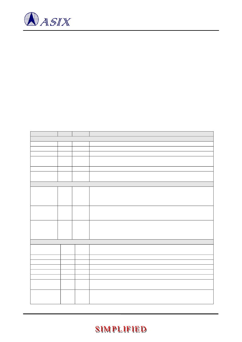
Table 1
: AX88772A 64-pin Pinout Description
Pin Name
Type
Pin No
Pin Description
USB Interface
DP
DM
VBUS
XTL12P
AB
AB
57
56
48
51
USB 2.0 data positive pin.
USB 2.0 data negative pin.
VBUS pin input. Please connect to USB bus power.
12Mhz
±
0.003%crystal or oscillator clock input. This clock is needed for
USB PHY transceiver to operate.
12Mhz crystal or oscillator clock output.
For USB PHY’s internal biasing. Please connect to analog GND through a
resistor (12.1Kohm
±
1%).
Serial EEPROM Interface
EEPROM Clock. EECK is an output clock to EEPROM to provide timing
reference for the transfer of EECS, and EEDIO signals. EECK only drive
high / low when access EEPROM otherwise keep at tri-state and internal
pull-down.
EEPROM Chip Select. EECS is asserted high synchronously with respect to
rising edge of EECK as chip select signal. EECS only drive high / low when
access EEPROM otherwise keep at tri-state and internal pull-down.
EEPROM Data In. EEDIO is the serial output data to EEPROM’s data input
pin and is synchronous with respect to the rising edge of EECK. EEDIO
only drive high / low when access EEPROM otherwise keep at tri-state and
internal pull-up.
Ethernet PHY Interface
25Mhz
±
0.005% crystal or oscillator clock input. This clock is needed for
the embedded 10/100M Ethernet PHY to operate.
25Mhz crystal or oscillator clock output.
Receive data input positive pin for both 10BASE-T and 100BASE-TX.
Receive data input negative pin for both 10BASE-T and 100BASE-TX.
Transmit data output positive pin for both 10BASE-T and 100 BASE-TX
Transmit data output negative pin for both 10BASE-T and 100 BASE-TX
For Ethernet PHY’s internal biasing. Please connect to GND through a
12.1Kohm
±
1% resistor.
Link status LED indicator. This pin drives low continuously when the
Ethernet link is up and drives low and high in turn (blinking) when Ethernet
PHY is in receiving or transmitting state.
I5/PD/S
I3
XTL12N
RREF
O3
AI
52
55
EECK
B5/PD/
T
35
EECS
B5/PD/
T
36
EEDIO
B5/PU/
T
37
XTL25P
I18
62
XTL25N
RXIP
RXIN
TXOP
TXON
RSET_BG
O18
AB
AB
AB
AB
AO
63
4
5
7
8
1
LINK_LED
O5
20
相關(guān)PDF資料 |
PDF描述 |
|---|---|
| AX88772ALF | USB 2.0 to 10/100M Fast Ethernet Controller |
| AX88172L | USB to Fast Ethernet/HomePNA Controller |
| AX88180 | High-Performance Non-PCI 32-bit 10/100/1000M Gigabit Ethernet Controller |
| AX88190P | 10/100BASE PCMCIA Fast Ethernet MAC Controller |
| AX88195P | 10/100BASE Local CPU Bus Fast Ethernet MAC Controller |
相關(guān)代理商/技術(shù)參數(shù) |
參數(shù)描述 |
|---|---|
| AX88772ALF | 制造商:ASIX Electronics Corporation 功能描述: |
| AX88772B | 制造商:ASIX 制造商全稱:ASIX 功能描述:AX88796C -- 低功耗 SPI或Non-PCI以太網(wǎng)控制器與方案 |
| AX88772BLF | 制造商:ASIX Electronics Corporation 功能描述: |
| AX88772BLI | 制造商:ASIX Electronics Corporation 功能描述: |
| AX88772C | 制造商:ASIX 制造商全稱:ASIX 功能描述:AX88796C -- 低功耗 SPI或Non-PCI以太網(wǎng)控制器與方案 |
發(fā)布緊急采購,3分鐘左右您將得到回復(fù)。