- 您現(xiàn)在的位置:買(mǎi)賣(mài)IC網(wǎng) > PDF目錄375359 > AQY221N2S PHOTOMOS RELAYS PDF資料下載
參數(shù)資料
| 型號(hào): | AQY221N2S |
| 英文描述: | PHOTOMOS RELAYS |
| 中文描述: | PHOTOMOS繼電器 |
| 文件頁(yè)數(shù): | 2/4頁(yè) |
| 文件大小: | 35K |
| 代理商: | AQY221N2S |
545
AQY221N2S
Item
Symbol
AQY221N2S
Condition
Input
LED operate current
Minimum
Typical
Maximum
Minimum
Typical
Maximum
Minimum
Typical
Maximum
Minimum
Typical
Maximum
I
Fon
0.9 mA
3.0mA
0.2 mA
0.85mA
I
L
= 80 mA
LED turn off current
I
Foff
I
L
= 80 mA
LED dropout voltage
V
F
1.14V (1.25 V at I
F
= 50mA)
1.5 V
I
F
= 5mA
Output
On resistance
R
on
9.5
12.5
I
F
= 80 mA
Within 1 s on time
I
F
= 0
V
B
= 0 V
f = 1 MHz
= 5mA
I
L
Output capacitance
Minimum
Typical
Maximum
Minimum
Typical
Maximum
Minimum
Typical
Maximum
C
out
1.0 pF
1.5 pF
Off state leakage current
I
Leak
0.01 nA
10 nA
I
= Max.
F
= 0
V
L
Transfer
characteristics
Switching
speed
Turn on
time*
T
on
0.03 ms
0.5 ms
I
V
F
= 5mA
= 10V
= 125
= 5mA
= 10V
= 125
L
R
L
Turn off
time*
Minimum
Typical
Maximum
Minimum
Typical
Maximum
Minimum
Typical
Maximum
T
off
0.03ms
0.2 ms
I
V
F
L
R
L
I/O capacitance
C
iso
0.8 pF
1.5pF
1,000M
f = 1MHz
V
B
= 0
Initial I/O isolation
resistance
R
iso
500V DC
2. Electrical characteristics
(Ambient temperature: 25°C
77°F
)
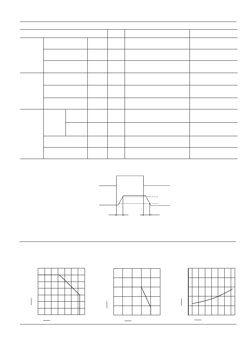
*Turn on/Turn off time
Toff
Input
Output
Ton
90%
10%
REFERENCE DATA
1. Load current vs. ambient temperature char-
acteristics
Allowable ambient temperature: –40°C to +85
–40°F to +185°F
0
-40
60
80
140
0
20
40
60
8085
100
-20
40
20
100
120
L
Ambient temperature,
°
C
0
5
10
15
20
25
0
20
40
60
8085
-40
-20
O
Ambient temperature,
°
C
0
80
200
10
20
Load voltage, V
30
40
50
0
40
120
160
L
°
C
2. Load current vs. Load voltage characteristics
Ambient temperature: 25°C
77°F
3. On resistance vs. ambient temperature char-
acteristics
Measured portion: between terminals 3 and 4
LED current: 5 mA; Load voltage: Max. (DC);
II
For Schematic and Wiring Diagrams, see Page 444. For Cautions for Use, see Page 449.
相關(guān)PDF資料 |
PDF描述 |
|---|---|
| AQY221N2SX | PHOTOMOS RELAYS |
| AQY221N2SZ | PHOTOMOS RELAYS |
| AQY221N3V | PhotoMOS RELAYS |
| AQY221N3VW | PhotoMOS RELAYS |
| AQY221N3VY | PhotoMOS RELAYS |
相關(guān)代理商/技術(shù)參數(shù) |
參數(shù)描述 |
|---|---|
| AQY-221N2S | 制造商:Panasonic 功能描述:Bulk |
| AQY221N2SJ | 制造商:Panasonic 功能描述:PN may be NE CE |
| AQY221N2SX | 功能描述:固態(tài)繼電器-PCB安裝 40v 120mA SOP Form A Norm-Open RoHS:否 制造商:Omron Electronics 控制電壓范圍: 負(fù)載電壓額定值:40 V 負(fù)載電流額定值:120 mA 觸點(diǎn)形式:1 Form A (SPST-NO) 輸出設(shè)備:MOSFET 封裝 / 箱體:USOP-4 安裝風(fēng)格:SMD/SMT |
| AQY-221N2SX | 制造商:Panasonic 功能描述:Bulk |
| AQY221N2SXJ | 制造商:Panasonic Electric Works 功能描述: |
發(fā)布緊急采購(gòu),3分鐘左右您將得到回復(fù)。