- 您現(xiàn)在的位置:買賣IC網(wǎng) > PDF目錄375328 > AN8267S (PANASONIC CORP) ECONOLINE: REC3-S_DRW(Z)/H4,H6 - Safety standards and approval: EN 60950 certified, rated for 250VAV (LVD test report)- Applied for Ul 1950 Component Recognised Certification- 3W DIP Package- 4kVDC & 6kVDC Isolation- Regulated Output- Continuous Short Circiut Protection Auto-Restarting PDF資料下載
參數(shù)資料
| 型號: | AN8267S |
| 廠商: | PANASONIC CORP |
| 元件分類: | 運動控制電子 |
| 英文描述: | ECONOLINE: REC3-S_DRW(Z)/H4,H6 - Safety standards and approval: EN 60950 certified, rated for 250VAV (LVD test report)- Applied for Ul 1950 Component Recognised Certification- 3W DIP Package- 4kVDC & 6kVDC Isolation- Regulated Output- Continuous Short Circiut Protection Auto-Restarting |
| 中文描述: | BRUSH DC MOTOR CONTROLLER, 1.5 A, PDSO16 |
| 封裝: | 0.300 INCH, PLASTIC, SOP-16 |
| 文件頁數(shù): | 4/5頁 |
| 文件大小: | 53K |
| 代理商: | AN8267S |
When the lock protective function is being activated, coil
current supply/stop intervals are about 1 : 7 in terms of time
ratio.
Assuming the external capacitor of the Pin4 to be of 1
μ
F,
the supply/stop time ratio is about 0.3sec. : 2sec.
Lock Protective Function ON/OFF Time Calculation Expres-
sion
Assuming the charging current to be Ich and the discharging
current to be I
DC
;
At charge time ;
At discharge time
Each value (typ.) of the AN8267S is ;
V
1
=4V Ich=9.5
μ
A
V
2
=0.95V I
DC
=1.3
μ
A
When C=1
μ
F ;
t
on
=0.32s C : External capacitor's capacity
t
off
=2.35s
4. Rotation output Pins2 and3
The Pins2 and 3 are of open collector output. The Pin2 is a
pulse output pin synchronized with a signal from the Hall ele-
ment. Therefore, the Pin2 is switched over depending on the
polarities of the Hall input Pins1 and 16.
Polarities of Pins2, 1, and 16
2. Occurrence of radio noises
When driving the motor with the AN8267S, radio noises
(noises which come out of the radio when the motor is driven
near it) may occur.
The radio noises are more likely to occur as the counter
electromotive power of the coil output pin rises more steeply.
So, they can be eliminated by attaching the external part men-
tioned in 1-2) above.
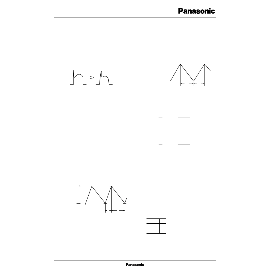
3. AN8267S lock protection
When the motor fan is locked, the AN8267S has a function
to protect the motor and IC. (lock protection operational prin-
ciple)
If the motor fan is locked, a sine wave signal is not input
from the Hall element any more and the potential of the Pin4
external capacitor increases. (Fig.5a)
During this period, the IC is still supplying the coil current
to rotate the motor fan. Then, if the voltage at the Pin4 reach-
es the reference voltage 1 set inside the IC, the electric charge
in the external capacitor of the Pin4 is discharged constantly,
thus reducing the voltage at the Pin4. (Fig.5b)
The IC stops supplying the coil current when this constant
current discharge starts. If the voltage at the Pin4 reaches the
reference voltage 2, the IC starts charging a constant current
to the external capacitor of the Pin4 and supplies the coil cur-
rent again, thus repeating the above-mentioned operation.
The external capacitor of the Pin4 is always kept in the dis-
charge state by a signal from the Hall element at the time of
stationary rotation.
I
Supplementary Explanation (Cont.)
Steep Rise
Gentle Rise
Fig.4
Reference Voltage 1 (V1)
Reference Voltage 2 (V2)
Fig.6
toff
ton
a
Reference Voltage 2
Reference Voltage 1
b
Fig.5
L
H
H
L
H
L
1
16
2
V
1
–V
2
=
∴
t on= (V
I ch dt =
∫
1
C
1
–V
2
)
I ch
I ch · ton
C
∫
V
1
–V
2
=
∴
t off= (V
I
DC
dt =
1
C
1
–V
2
)
I
DC
I ch · toff
C
相關(guān)PDF資料 |
PDF描述 |
|---|---|
| AN826 | RECOMMENDED MINIMUM PADS FOR SC-70: 3-LEAD |
| AN8353UB | High Efficiency Car Dashboard Dimmer IC |
| AN8377N | 3-channel Linear Driver |
| AN8473SA | Spindle motor driver IC for optical disk |
| AN8480NSB | 3-phase full-wave motor driver IC |
相關(guān)代理商/技術(shù)參數(shù) |
參數(shù)描述 |
|---|---|
| AN827-12J | 制造商:undefined 功能描述: |
| AN827-4D | 制造商: 功能描述: 制造商:undefined 功能描述: |
| AN827-6D | 制造商: 功能描述: 制造商:undefined 功能描述: |
| AN8280 | 制造商:未知廠家 制造商全稱:未知廠家 功能描述:主導(dǎo)軸馬達直接驅(qū)動電路 |
| AN8281S | 制造商:未知廠家 制造商全稱:未知廠家 功能描述:主導(dǎo)軸馬達直接驅(qū)動電路 |
發(fā)布緊急采購,3分鐘左右您將得到回復(fù)。