- 您現(xiàn)在的位置:買賣IC網(wǎng) > PDF目錄375271 > AFE1144 Circular Connector; No. of Contacts:15; Series:MS27467; Body Material:Aluminum; Connecting Termination:Crimp; Connector Shell Size:15; Circular Contact Gender:Pin; Circular Shell Style:Straight Plug; Insert Arrangement:15-15 RoHS Compliant: No PDF資料下載
參數(shù)資料
| 型號(hào): | AFE1144 |
| 元件分類: | 圓形連接器 |
| 英文描述: | Circular Connector; No. of Contacts:15; Series:MS27467; Body Material:Aluminum; Connecting Termination:Crimp; Connector Shell Size:15; Circular Contact Gender:Pin; Circular Shell Style:Straight Plug; Insert Arrangement:15-15 RoHS Compliant: No |
| 中文描述: | HDSL / MDSL模擬前端 |
| 文件頁(yè)數(shù): | 10/11頁(yè) |
| 文件大?。?/td> | 114K |
| 代理商: | AFE1144 |
10
AFE1144
DISCUSSION OF
SPECIFICATIONS
UNCANCELLED ECHO
A key measure of transceiver performance is uncancelled
echo. Uncancelled echo is the summation of all of the errors
in the transmit and receive paths of the AFE1144. It includes
effects of linearity, distortion and noise. Uncancelled echo is
tested in production by Burr-Brown with a circuit that is
similar to the one shown in Figure 7, Uncancelled Echo Test
Diagram.
The measurement of uncancelled echo is made as follows.
The AFE is connected to an output circuit including a typical
1:2 line transformer. The line is simulated by a 135
resistor. Symbol sequences are generated by the tester and
applied both to the AFE and to the input of an adaptive filter.
The output of the adaptive filter is subtracted from the AFE
output to form the uncanceled echo signal. Once the filter
taps have converged, the RMS value of the uncancelled echo
is calculated. Since there is no far-end signal source or
additive line noise, the uncanceled echo contains only noise
and linearity errors generated in the transmit and receive
sections of the AFE1144.
The data sheet value for uncancelled echo is the ratio of
the RMS uncanceled echo (referred to the receiver input
through the receiver gain) to the nominal transmitted signal
(13.5dBm into 135
, or 1.74Vrms). This echo value is
measured under a variety of conditions: with loopback
enabled (line input disconnected); with loopback disabled
under all receiver gain ranges; and with the line shorted
(S
1
closed in Figure 7).
POWER DISSIPATION
Approximately 80% of the power dissipation in the AFE1144
is in the analog circuitry, and this component does not
change with clock frequency. However, the power dissipa-
tion in the digital circuitry does decrease with lower clock
frequency. In addition, the power dissipation in the digital
section is decreased when operating from a smaller supply
voltage, such as 3.3V. (The analog supply, AV
DD
, must
remain in the range 4.75V to 5.25V).
The power dissipation listed in the specifications section
applies under these normal operating conditions: 5V Analog
Power Supply; 3.3V Digital Power Supply; standard 13.5dBm
delivered to the line; and a pseudorandom equiprobable
sequence of HDSL output pulses. The power dissipation
specifications includes all power dissipated in the AFE1144,
it does not include power dissipated in the external load.
The external power is 16.5dBm: 13.5dBm to the line and
13.5dBm to the impedance matching resistors. The external
load power of 16.5dBm is 45mW. The typical power dissi-
pation in the AFE1144 under various conditions is shown in
Table II.
The T1 and E1 power measurements in the Specifications
are made with the output circuit shown in Figure 7. This
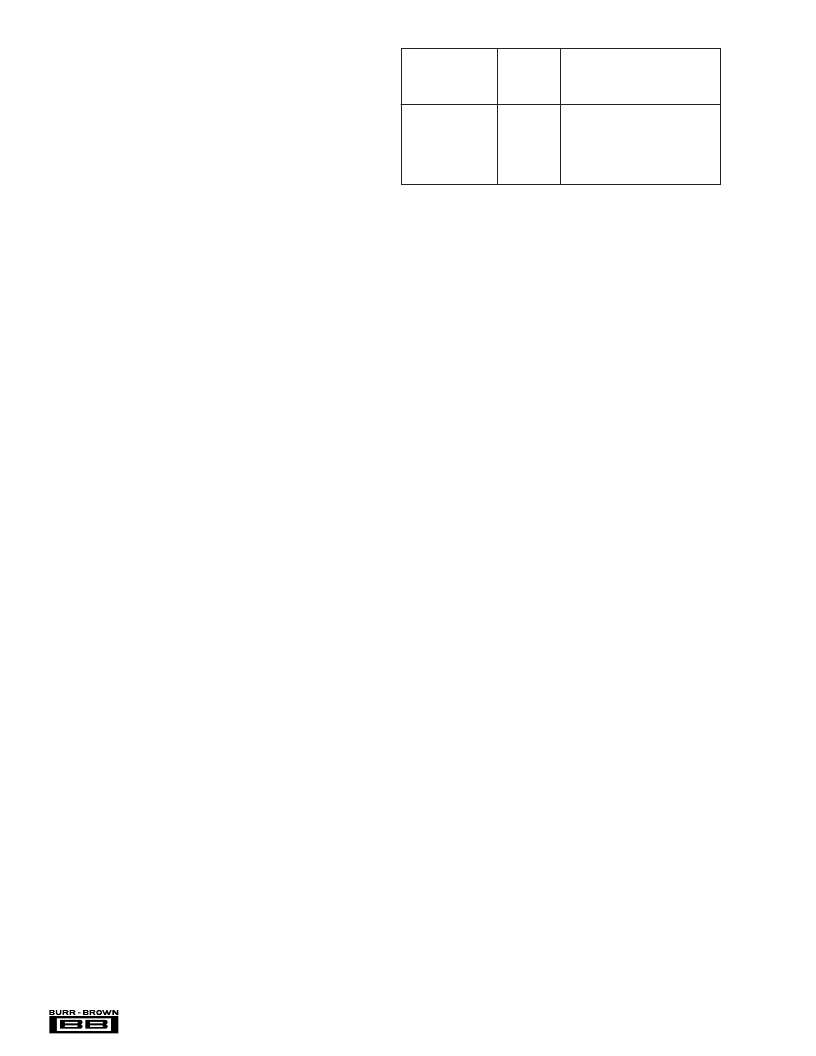
TYPICAL POWER
DISSIPATION
IN THE AFE1144
(mW)
BIT RATE
PER AFE1144
(Symbols/sec)
DVDD
(V)
584 (E1)
584 (E1)
392 (T1)
392 (T1)
146 (E1/4)
146 (E1/4)
3.3
5
3.3
5
3.3
5
250
300
240
270
230
245
TABLE II. Typical Power Dissipation.
circuit uses a 1:2 transformer. The power measurements
shown in Table II use an equivalent resistive load instead of
the transformer to eliminate frequency dependent imped-
ances of the transformer.
LAYOUT
The analog front end of an HDSL system has two conflicting
requirements. It must accept and deliver moderately high
rate digital signals and it must generate, drive, and convert
precision analog signals. To achieve optimal system perfor-
mance with the AFE1144, both the digital and the analog
sections must be treated carefully in board layout design.
The power supply for the digital section of the AFE1144 can
range from 3.3V to 5V. This supply should be decoupled to
digital ground with ceramic 0.1
μ
F capacitors placed as close
to DGND and DV
DD
as possible. One capacitor should be
placed between pins 3 and 4 and the second capacitor
between pins 11 and 12. Ideally, both a digital power supply
plane and a digital ground plane should run up to and
underneath the digital pins of the AFE1144 (pins 5 through
10). However, DV
DD
may be supplied by a wide printed
circuit board (PCB) trace. A digital ground plane underneath
all digital pins is strongly recommended.
The remaining portion of the AFE1144 should be considered
analog. All AGND pins should be connected directly to a
common analog ground plane and all AV
DD
pins should be
connected to an analog 5V power plane. Both of these planes
should have a low impedance path to the power supply. The
analog power supply pins should be decoupled to analog
ground with ceramic 0.1
μ
F capacitors placed as close to the
AFE1144 as possible. One 10
μ
F tantalum capacitor should
also be used with each AFE1144 between the analog supply
and analog ground.
Ideally, all ground planes and traces and all power planes
and traces should return to the power supply connector
before being connected together (if necessary). Each ground
and power pair should be routed over each other, should not
overlap any portion of another pair, and the pairs should be
separated by a distance of at least 0.25 inch (6mm). One
exception is that the digital and analog ground planes should
be connected together underneath the AFE1144 by a small
trace.
相關(guān)PDF資料 |
PDF描述 |
|---|---|
| AFE1144E | Circular Connector; No. of Contacts:15; Series:MS27467; Body Material:Aluminum; Connecting Termination:Crimp; Connector Shell Size:15; Circular Contact Gender:Socket; Circular Shell Style:Straight Plug; Insert Arrangement:15-15 RoHS Compliant: No |
| AFE1203 | Circular Connector; No. of Contacts:15; Series:MS27467; Body Material:Aluminum; Connecting Termination:Crimp; Connector Shell Size:15; Circular Contact Gender:Socket; Circular Shell Style:Straight Plug; Insert Arrangement:15-15 RoHS Compliant: No |
| AFE1203E | LJT 18C 18#20 PIN PLUG |
| AFE1205 | LJT 18C 18#20 PIN PLUG |
| AFE1205E | Circular Connector; No. of Contacts:18; Series:MS27467; Body Material:Aluminum; Connecting Termination:Crimp; Connector Shell Size:15; Circular Contact Gender:Pin; Circular Shell Style:Straight Plug; Insert Arrangement:15-18 RoHS Compliant: No |
相關(guān)代理商/技術(shù)參數(shù) |
參數(shù)描述 |
|---|---|
| AFE1144E | 制造商:Rochester Electronics LLC 功能描述:- Bulk |
| AFE1144E/1K | 制造商:未知廠家 制造商全稱:未知廠家 功能描述:xDSL Interface |
| AFE1200 | 制造商:ARTESYN 制造商全稱:Artesyn Technologies 功能描述:Single output |
| AFE1200-96S24NA | 制造商:ARTESYN 制造商全稱:Artesyn Technologies 功能描述:Single output |
| AFE1200-96S48NA | 制造商:Johnson Components 功能描述:48V Single |
發(fā)布緊急采購(gòu),3分鐘左右您將得到回復(fù)。