- 您現(xiàn)在的位置:買賣IC網(wǎng) > PDF目錄374045 > ADV7152LS220 (ANALOG DEVICES INC) CMOS 220 MHz True-Color Graphics Triple 10-Bit Video RAM-DAC PDF資料下載
參數(shù)資料
| 型號: | ADV7152LS220 |
| 廠商: | ANALOG DEVICES INC |
| 元件分類: | 顯示控制器 |
| 英文描述: | CMOS 220 MHz True-Color Graphics Triple 10-Bit Video RAM-DAC |
| 中文描述: | PALETTE-DAC DSPL CTLR, PQFP100 |
| 封裝: | PLASTIC, QFP-100 |
| 文件頁數(shù): | 2/32頁 |
| 文件大?。?/td> | 454K |
| 代理商: | ADV7152LS220 |
第1頁當(dāng)前第2頁第3頁第4頁第5頁第6頁第7頁第8頁第9頁第10頁第11頁第12頁第13頁第14頁第15頁第16頁第17頁第18頁第19頁第20頁第21頁第22頁第23頁第24頁第25頁第26頁第27頁第28頁第29頁第30頁第31頁第32頁
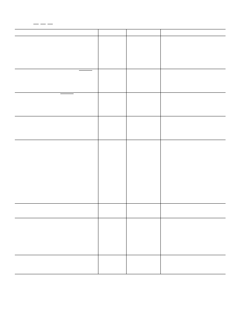
REV. B
–2–
ADV7152–SPECIFICATIONS
(V
AA1
= +5 V; V
REF
= +1.235 V; R
SET
= 280
V
. IOR, IOG IOB (R
L
= 37.5
V
,
C
L
= 10 pF);
IOR
,
IOG
,
IOB
= GND. All specifications T
MN
to T
MAX2
unless otherwse noted.)
Parameter
All Versions
Unit
T est Conditions/Comments
ST AT IC PERFORMANCE
Resolution (Each DAC)
Accuracy (Each DAC)
Integral Nonlinearity
Differential Nonlinearity
Gray Scale Error
Coding
DIGIT AL INPUT S (Excluding CLOCK ,
CLOCK
)
Input High Voltage, V
INH
Input Low Voltage, V
INL
Input Current, I
IN
Input Capacitance, C
IN
CLOCK INPUT S (CLOCK ,
CLOCK
)
Input High Voltage, V
INH
Input Low Voltage, V
INL
Input Current, I
IN
Input Capacitance, C
IN
DIGIT AL OUT PUT S
Output High Voltage, V
OH
Output Low Voltage, V
OL
Floating-State Leakage Current
Floating-State Output Capacitance
ANALOG OUT PUT S
Gray Scale Current Range
Output Current
White Level Relative to Blank
White Level Relative to Black
Black Level Relative to Blank
Blank Level on IOR, IOB
Blank Level on IOG
Sync Level on IOG
LSB Size
DAC-to-DAC Matching
Output Compliance, V
OC
Output Impedance, R
OUT
Output Capacitance, C
OUT
VOLT AGE REFERENCE
Voltage Reference Range, V
REF
Input Current, I
VREF
POWER REQUIREMENT S
V
AA
I
AA3
I
AA
I
AA
I
AA
I
AA
Power Supply Rejection Ratio
DYNAMIC PERFORMANCE
Clock and Data Feedthrough
4, 5
Glitch Impulse
DAC-to-DAC Crosstalk
6
10
Bits
±
1
±
1
±
5
LSB max
LSB max
% Gray Scale max
Binary
Guaranteed Monotonic
2
0.8
±
10
10
V min
V max
μ
A max
pF typ
V
IN
= 0.4 V or 2.4 V
V
AA
– 1.0
V
AA
– 1.6
±
10
10
V min
V max
μ
A max
pF typ
V
IN
= 0.4 V or 2.4 V
2.4
0.4
20
20
V min
V max
μ
A max
pF typ
I
SOURCE
= 400
μ
A
I
SINK
= 3.2 mA
15/22
mA min/max
17.69/20.40
16.74/18.50
0.95/1.90
0/50
6.29/8.96
0/50
17.22
3
0/+1.4
100
30
mA min/max
mA min/max
mA min/max
μ
A min
mA min/max
μ
A min/max
μ
A typ
% max
V min/V max
k
typ
pF max
T ypically 19.05 mA
T ypically 17.62 mA
T ypically 1.44 mA
T ypically 5
μ
A
T ypically 7.62 mA
T ypically 5
μ
A
T ypically 1%
I
OUT
= 0 mA
1.14/1.26
+5
V min/V max
μ
A typ
V
REF
= 1.235 V for Specified Performance
5
400
370
350
330
315
0.5
V nom
mA max
mA max
mA max
mA max
mA max
%/% max
220 MHz Parts
170 MHz Parts
135 MHz Parts
110 MHz Parts
85 MHz Parts
T ypically 0.12%/%, COMP = 0.1
μ
F
–30
50
–23
dB typ
pV secs typ
dB typ
NOT ES
1
±
5% for all versions.
2
T emperature range (T
to T
): 0
°
C to +70
°
C; T
(Silicon Junction T emperature)
≤
100
°
C.
3
Pixel Port is continuously clocked with data corresponding to a linear ramp. T
= 100
°
C.
4
Clock and data feedthrough is a function of the amount of overshoot and undershoot on the digital inputs. Glitch impulse includes clock and data feedthrough.
5
T T L input values are 0 to 3 volts, with input rise/fall times
≤
3 ns, measured the 10% and 90% points. T iming reference points at 50% for inputs and outputs.
6
DAC-to-DAC crosstalk is measured by holding one DAC high while the other two are making low-to-high and high-to-low transitions.
Specifications subject to change without notice.
相關(guān)PDF資料 |
PDF描述 |
|---|---|
| ADV7160 | 96-Bit, 220 MHz True-Color Video RAM-DAC(96位,220MHz,真彩色視頻RAM-D/A轉(zhuǎn)換器) |
| ADV7162 | 96-Bit, 220 MHz True-Color Video RAM-DAC(96位,220MHz,真彩色視頻RAM-D/A轉(zhuǎn)換器) |
| ADV7162KS140 | 96-Bit, 220 MHz True-Color Video RAM-DAC |
| ADV7162KS170 | 96-Bit, 220 MHz True-Color Video RAM-DAC |
| ADV7162KS220 | 96-Bit, 220 MHz True-Color Video RAM-DAC |
相關(guān)代理商/技術(shù)參數(shù) |
參數(shù)描述 |
|---|---|
| ADV7152LS85 | 制造商:AD 制造商全稱:Analog Devices 功能描述:CMOS 220 MHz True-Color Graphics Triple 10-Bit Video RAM-DAC |
| ADV7160 | 制造商:AD 制造商全稱:Analog Devices 功能描述:96-Bit, 220 MHz True-Color Video RAM-DAC |
| ADV7160KS140 | 制造商:Analog Devices 功能描述: 制造商:Rochester Electronics LLC 功能描述:220 MHZ VIDEO RAM DAC I.C. - Bulk |
| ADV7160KS170 | 制造商:Analog Devices 功能描述:DAC 3-CH Segment 10-bit 160-Pin MQFP 制造商:Rochester Electronics LLC 功能描述:220 MHZ VIDEO RAM DAC I.C. - Bulk |
| ADV7160KS220 | 制造商:Analog Devices 功能描述: 制造商:Rochester Electronics LLC 功能描述: |
發(fā)布緊急采購,3分鐘左右您將得到回復(fù)。