- 您現(xiàn)在的位置:買賣IC網 > PDF目錄374045 > ADV7121 (Analog Devices, Inc.) CMOS 80 MHz, Triple 10-Bit Video DACs PDF資料下載
參數(shù)資料
| 型號: | ADV7121 |
| 廠商: | Analog Devices, Inc. |
| 英文描述: | CMOS 80 MHz, Triple 10-Bit Video DACs |
| 中文描述: | 80兆赫的CMOS,三路10位視頻DAC |
| 文件頁數(shù): | 9/12頁 |
| 文件大小: | 196K |
| 代理商: | ADV7121 |
ADV7121/ADV7122
–9–
REV. B
Video Synchronization & Control
T he ADV7122 has a single composite sync (
SYNC
) input con-
trol. Many graphics processors and CRT controllers have the
ability of generating horizontal sync (HSYNC), vertical sync
(VSYNC) and composite
SYNC
.
In a graphics system which does not automatically generate a
composite
SYNC
signal, the inclusion of some additional logic
circuitry will enable the generation of a composite
SYNC
signal.
T he sync current is internally connected directly to the IOG
output, thus encoding video synchronization information onto
the green video channel. If it is not required to encode sync in-
formation onto the ADV7122, the
SYNC
input should be tied
to logic low.
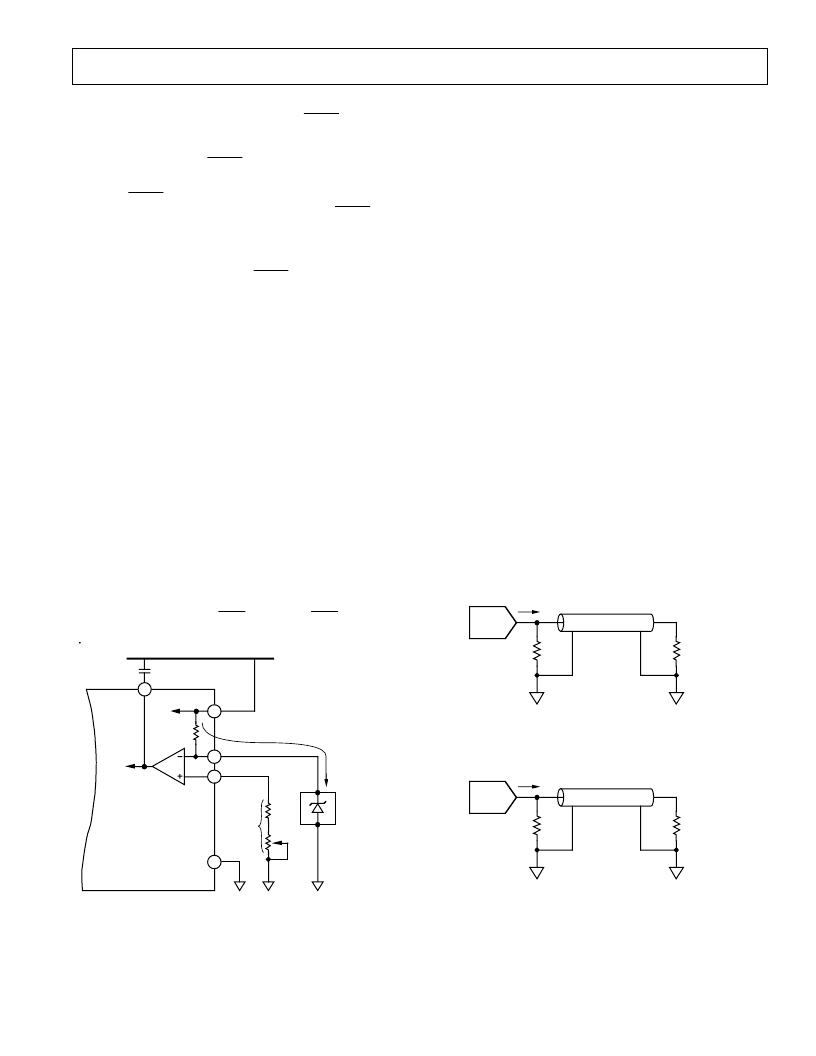
Reference Input
An external 1.23 V voltage reference is required to drive the
ADV7121/ADV7122. T he AD589 from Analog Devices is an
ideal choice of reference. It is a two-terminal, low cost, tempera-
ture compensated bandgap voltage reference which provides a
fixed 1.23 V output voltage for input currents between 50
μ
A
and 5 mA. Figure 4 shows a typical reference circuit connection
diagram. T he voltage reference gets its current drive from the
ADV7121/ADV7122’s V
AA
through an onboard 1 k
resistor to
the V
REF
pin. A 0.1
μ
F ceramic capacitor is required between
the COMP pin and V
AA
. T his is necessary so as to provide com-
pensation for the internal reference amplifier.
A resistance R
SET
connected between FS ADJUST and GND
determines the amplitude of the output video level according to
Equations 1 and 2 for the ADV7122 and Equation 3 for the
ADV7121:
IOG
* (
mA
) = 12,082
×
V
REF
(V)/
R
SET
(
) (1)
IOR, IOB (mA) =
8,628
×
V
REF
(V)/R
SET
(
)
IOR, IOG, IOB (mA) =
7,969
×
V
REF
(V)/R
SET
(
)
*O
nly applies to the ADV7122 when
SYNC
is being used. If
SYNC
is not being
encoded onto the green channel, then Equation 1 will be similar to Equation 2.
(2)
(3)
TO DACs
V
AA
V
REF
GND
1k
FS ADJUST
R
SET
560
500
100
ANALOG POWER PLANE
COMP
0.01
μ
F
5V
+
I
REF
≈
5mA
AD589
(1.235V
VOLTAGE
REFERENCE)
ADV7121/ADV7122*
*ADDITIONAL CIRCUITRY, INCLUDING
DECOUPLING COMPONENTS,
EXCLUDED FOR CLARIITY
Figure 4. Reference Circuit
Using a variable value of R
SET
, as shown in Figure 4, allows for
accurate adjustment of the analog output video levels. Use of a
fixed 560
R
SET
resistor yields the analog output levels as quoted
in the specification page. T hese values typically correspond to
the RS-343A video waveform values as shown in Figure 3.
D/A Converters
T he ADV7121/ADV7122 contains three matched 10-bit D/A
converters. T he DACs are designed using an advanced, high
speed, segmented architecture. T he bit currents corresponding
to each digital input are routed to either the analog output (bit
= “1”) or GND (bit = “0”) by a sophisticated decoding scheme.
As all this circuitry is on one monolithic device, matching be-
tween the three DACs is optimized. As well as matching, the
use of identical current sources in a monolithic design guaran-
tees monotonicity and low glitch. T he onboard operational am-
plifier stabilizes the full-scale output current against temperature
and power supply variations.
Analog Outputs
T he ADV7121/ADV7122 has three analog outputs, correspond-
ing to the red, green and blue video signals.
T he red, green and blue analog outputs of the ADV7121/
ADV7122 are high impedance current sources. Each one of
these three RGB current outputs is capable of directly driving a
37.5
load, such as a doubly terminated 75
coaxial cable.
Figure 5a shows the required configuration for each of the three
RGB outputs connected into a doubly terminated 75
load.
T his arrangement will develop RS-343A video output voltage
levels across a 75
monitor.
A suggested method of driving RS-170 video levels into a 75
monitor is shown in Figure 5b. T he output current levels of the
DACs remain unchanged, but the source termination resistance,
Z
S
, on each of the three DACs is increased from 75
to 150
.
DACs
IOR, IOG, IOB
Z
O
= 75
(CABLE)
Z
S
= 75
(SOURCE
TERMINATION)
TERMINATION REPEATED THREE TIMES
FOR RED, GREEN AND BLUE DACs
Z
L
= 75
(MONITOR)
Figure 5a. Analog Output Termination for RS-343A
DACs
IOR, IOG, IOB
Z
O
= 75
(CABLE)
Z
= 150
(SOURCE
TERMINATION)
TERMINATION REPEATED THREE TIMES
FOR RED, GREEN AND BLUE DACs
Z
L
= 75
(MONITOR)
Figure 5b. Analog Output Termination for RS-170
相關PDF資料 |
PDF描述 |
|---|---|
| ADV7122KP30 | CMOS 80 MHz, Triple 10-Bit Video DACs |
| ADV7122KP50 | CMOS 80 MHz, Triple 10-Bit Video DACs |
| ADV7122KP80 | CMOS 80 MHz, Triple 10-Bit Video DACs |
| ADV7121KN30 | CMOS 80 MHz, Triple 10-Bit Video DACs |
| ADV7122 | 80 MHz, Triple 10-Bit Video DACs(80MHz,三通道10位視頻D/A轉換器) |
相關代理商/技術參數(shù) |
參數(shù)描述 |
|---|---|
| ADV7121JN30 | 制造商:未知廠家 制造商全稱:未知廠家 功能描述:Video DAC without Color Palette |
| ADV7121JN50 | 制造商:未知廠家 制造商全稱:未知廠家 功能描述:Video DAC without Color Palette |
| ADV7121JN80 | 制造商:未知廠家 制造商全稱:未知廠家 功能描述:Video DAC without Color Palette |
| ADV7121KN30 | 制造商:Analog Devices 功能描述: |
| ADV7121KN50 | 制造商:Rochester Electronics LLC 功能描述:- Bulk |
發(fā)布緊急采購,3分鐘左右您將得到回復。