- 您現(xiàn)在的位置:買賣IC網(wǎng) > PDF目錄373980 > ADE7754 (Analog Devices, Inc.) ADE7754 PDF資料下載
參數(shù)資料
| 型號(hào): | ADE7754 |
| 廠商: | Analog Devices, Inc. |
| 英文描述: | ADE7754 |
| 中文描述: | ADE7754 |
| 文件頁(yè)數(shù): | 43/44頁(yè) |
| 文件大小: | 630K |
| 代理商: | ADE7754 |
第1頁(yè)第2頁(yè)第3頁(yè)第4頁(yè)第5頁(yè)第6頁(yè)第7頁(yè)第8頁(yè)第9頁(yè)第10頁(yè)第11頁(yè)第12頁(yè)第13頁(yè)第14頁(yè)第15頁(yè)第16頁(yè)第17頁(yè)第18頁(yè)第19頁(yè)第20頁(yè)第21頁(yè)第22頁(yè)第23頁(yè)第24頁(yè)第25頁(yè)第26頁(yè)第27頁(yè)第28頁(yè)第29頁(yè)第30頁(yè)第31頁(yè)第32頁(yè)第33頁(yè)第34頁(yè)第35頁(yè)第36頁(yè)第37頁(yè)第38頁(yè)第39頁(yè)第40頁(yè)第41頁(yè)第42頁(yè)當(dāng)前第43頁(yè)第44頁(yè)

REV. PrG 01/03
PRELIMINARY TECHNICAL DATA
ADE7754
–
43
–
Interrupt Status Register (10h) / Reset Interrupt Status Register (11h)
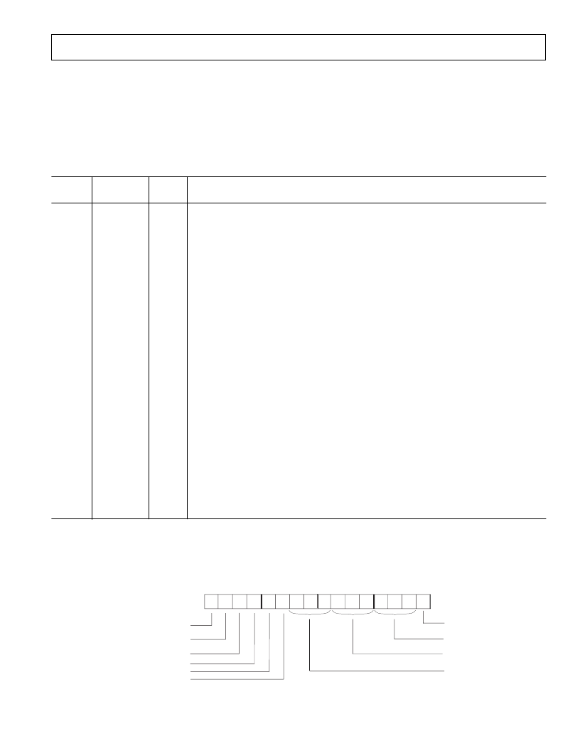
The Interrupt Status Register is used to determine the source of an interrupt event. When an interrupt event occurs in the
ADE7754, the corresponding flag in the Interrupt Status Register is set logic high. The
IRQ
pin will go active low if the
corresponding bit in the Interrupt Mask register is set logic high. When the MCU services the interrupt, it must first carry
out a read from the Interrupt Status Register to determine the source of the interrupt. All the interrupts in the Interrupt Status
Register stay at their logic high state after an event occurs. The state of the interrupt bit in the Interrupt Status register is reset
to its default value once the Reset Interrupt Status register is read.
Table XVII STATUS Register
Bit
Location
Interrupt
Flag
Default
Value
Event
Description
0
AEHF
0
Indicates that an interrupt was caused by the 0 to 1 transition of the MSB of the AENERGY
register (i.e. the AENERGY register is half-full)
Indicates that an interrupt was caused by a SAG on the line voltage of the Phase A
Indicates that an interrupt was caused by a SAG on the line voltage of the Phase B
Indicates that an interrupt was caused by a SAG on the line voltage of the Phase C
Indicates that an interrupt was caused by a missing zero crossing on the line voltage of the
Phase A
Indicates that an interrupt was caused by a missing zero crossing on the line voltage of the
Phase B
Indicates that an interrupt was caused by a missing zero crossing on the line voltage of the
Phase C
Indicates a detection of rising zero crossing in the voltage channel of the phase A
Indicates a detection of rising zero crossing in the voltage channel of the phase B
Indicates a detection of rising zero crossing in the voltage channel of the phase C
In Line energy accumulation, it indicates the end of an integration over an integer number
of half line cycles (LINCYC)
—
see
Energy Calibration
Indicates that the ADE7754 has been reset
Indicates that an interrupt was caused when the selected voltage input is above the value
in the PKVLV register.
Indicates that an interrupt was caused when the selected current input is above the value
in the PKILV register.
Indicates that new data is present in the Waveform Register.
Indicates that an interrupt was caused by the 0 to 1 transition of the MSB of the
VAENERGY register (i.e. the VAENERGY register is half-full)
1
2
3
4
SAGA
SAGB
SAGC
ZXTOA
0
0
0
0
5
ZXTOB
0
6
ZXTOC
0
7
8
9
Ah
ZXA
ZXB
ZXC
LENERGY
0
0
0
0
Bh
Ch
RESET
PKV
0
0
Dh
PKI
0
Eh
Fh
WFSM
VAEHF
0
0
INTERRUPT STATUS REGISTER*
ADDR: 10h
0
1
2
3
4
5
6
7
0
0
0
0
0
0
0
0
8
9
A
B
C
D
E
F
0
0
0
0
0
0
0
0
(Apparent Energy Register HVAEHF
AEHF
SAG
(SAG Event Detect)
ZX
(Zero Crossing Time out Detection)
WFMP
(New Waveform Sample Ready)
*Register contents show power on defaults
LENERGY
(End of the LAENERGY and LVAENERGY accumulation)
ZX
(Zero Crossing Detection)
RESET
PKI
(Current channel Peak detection)
(Voltage channel Peak detecPKV
相關(guān)PDF資料 |
PDF描述 |
|---|---|
| ADE7754AR | ADE7754 |
| ADE7754ARRL | ADE7754 |
| ADE7755AN-REF | Energy Metering IC with Pulse Output |
| ADE7755ARSRL | Energy Metering IC with Pulse Output |
| ADE7755 | Energy Metering IC with Pulse Output |
相關(guān)代理商/技術(shù)參數(shù) |
參數(shù)描述 |
|---|---|
| ADE7754AR | 制造商:Analog Devices 功能描述:Energy Measurement 24-Pin SOIC W 制造商:Rochester Electronics LLC 功能描述:THREE PHASE ENERGY METER IC W/WATT & VA - Bulk 制造商:Analog Devices 功能描述:IC ENERGY METER |
| ADE7754ARRL | 制造商:Analog Devices 功能描述:Energy Measurement 24-Pin SOIC W T/R 制造商:Rochester Electronics LLC 功能描述:THREE PHASE ENERGY METER IC W/WATT & VA - Bulk |
| ADE7754ARZ | 功能描述:IC ENERGY METERING 3PHASE 24SOIC RoHS:是 類別:集成電路 (IC) >> PMIC - 能量測(cè)量 系列:- 產(chǎn)品培訓(xùn)模塊:Lead (SnPb) Finish for COTS Obsolescence Mitigation Program 標(biāo)準(zhǔn)包裝:2,500 系列:* |
| ADE7754ARZRL | 功能描述:IC ENERGY METERING 3PHASE 24SOIC RoHS:是 類別:集成電路 (IC) >> PMIC - 能量測(cè)量 系列:- 產(chǎn)品培訓(xùn)模塊:Lead (SnPb) Finish for COTS Obsolescence Mitigation Program 標(biāo)準(zhǔn)包裝:2,500 系列:* |
| ADE7755 | 制造商:AD 制造商全稱:Analog Devices 功能描述:Energy Metering IC with Pulse Output |
發(fā)布緊急采購(gòu),3分鐘左右您將得到回復(fù)。