- 您現(xiàn)在的位置:買賣IC網(wǎng) > PDF目錄373979 > ADDC02828 (Analog Devices, Inc.) 270V/100W DC/DC Converter with Integral EMI Filter(帶積分EMI濾波器的DC-DC轉(zhuǎn)換器) PDF資料下載
參數(shù)資料
| 型號(hào): | ADDC02828 |
| 廠商: | Analog Devices, Inc. |
| 英文描述: | 270V/100W DC/DC Converter with Integral EMI Filter(帶積分EMI濾波器的DC-DC轉(zhuǎn)換器) |
| 中文描述: | 270V/100W直流/直流轉(zhuǎn)換器積分EMI過濾器(帶積分的EMI濾波器的的DC - DC轉(zhuǎn)換器) |
| 文件頁數(shù): | 3/16頁 |
| 文件大?。?/td> | 175K |
| 代理商: | ADDC02828 |
ADDC02828SA
REV. 0
–3–
ABSOLUT E MAX IMUM RAT INGS*
INHIBIT . . . . . . . . . . . . . . . . . . . . . . . . . . 50 V dc, –0.5 V dc
SYNC . . . . . . . . . . . . . . . . . . . . . . . . . . . . 8.0 V dc, –0.5 V dc
I
SHARE
. . . . . . . . . . . . . . . . . . . . . . . . . . . . . 6 V dc, –0.5 V dc
T EMP . . . . . . . . . . . . . . . . . . . . . . . . . . . . 12 V dc, –0.3 V dc
Common-Mode Voltage, Input to Output . . . . . . . . . 500 V dc
Lead Soldering T emp (10 sec) . . . . . . . . . . . . . . . . . . . +300
°
C
Storage T emperature . . . . . . . . . . . . . . . . . . –65
°
C to +150
°
C
Maximum Junction T emperature . . . . . . . . . . . . . . . . . +150
°
C
Maximum Case Operating T emperature . . . . . . . . . . . +125
°
C
*Absolute maximum ratings are limiting values, to be applied individually, and
beyond which the serviceability of the circuit may be impaired. Functional
operability under any of these conditions is not necessarily implied. Exposure of
absolute maximum rating conditions for extended periods of time may affect
device reliability.
ORDE RING GUIDE
Operating
T emperature
Range (Case)
Device
Description
ADDC02828SAK V
ADDC02828SAT V
ADDC02828SAT V/883B*
–40
°
C to +85
°
C
–55
°
C to +90
°
C
–55
°
C to +125
°
C Hermetic Package
Hermetic Package
Hermetic Package
*Contact factory.
E X PLANAT ION OF T E ST LE VE LS
T est Level
I
–
II
–
100% production tested.
100% production tested at +25
°
C, and sample tested at
specified temperatures.
Sample tested only.
Parameter is guaranteed by design and characterization
testing.
Parameter is a typical value only.
All devices are 100% production tested at +25
°
C. 100%
production tested at temperature extremes for military
temperature devices; guaranteed by design and charac-
terization testing for industrial devices.
III –
IV –
V
VI –
–
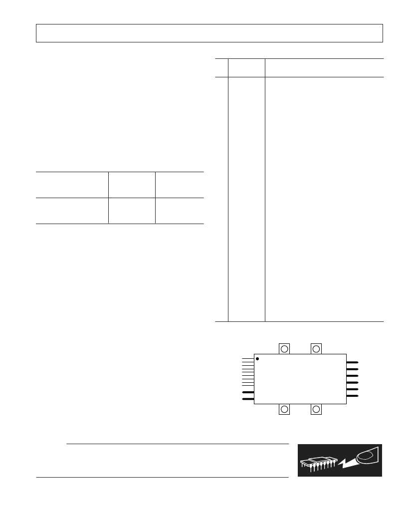
PIN FUNCT ION DE SCRIPT IONS
Pin
No.
Name
Function
1
–SENSE
Feedback loop connection for remote sensing
output voltage. Must always be connected to
output return for proper operation.
Feedback loop connection for remote sensing
output voltage. Must always be connected to
+V
OUT
for proper operation.
Adjusts output voltage setpoint.
Indicates output voltage is within
±
5% of
nominal. Active high referenced to –SENSE
(Pin 1).
Low level dc auxiliary voltage supply refer-
enced to input return (Pin 10).
Power Supply Inhibit. Active low and refer-
enced to input return (Pin 10).
Clock synchronization input for multiple units;
referenced to input return (Pin 10).
Current share pin that allows paralleled units
to share current typically within
±
5% at full
load; referenced to input return (Pin 10).
Case temperature indicator and temperature
shutdown override; referenced to input return
(Pin 10).
Input Return.
+28 V Nominal Input Bus.
+28 V dc Output.
+28 V dc Output.
Output Sense Reference.
Output Sense Reference.
Output Return.
Output Return.
2
+SENSE
3
4
ADJUST
ST AT US
5
V
AUX
6
INHIBIT
7
SYNC
8
I
SHARE
9
T EMP
10
11
12
13
14
15
16
17
–V
IN
+V
IN
+V
OUT
+V
OUT
SENSE
REF
SENSE
REF
RET URN
RET URN
PIN CONFIGURAT ION
1
11
12
17
TOP
VIEW
C AUT ION
ESD (electrostatic discharge) sensitive device. Electrostatic charges as high as 4000 V readily
accumulate on the human body and test equipment and can discharge without detection.
T herefore, proper ESD precautions are recommended to avoid performance degradation or loss
of functionality.
WARNING!
ESD SENSITIVE DEVICE
相關(guān)PDF資料 |
PDF描述 |
|---|---|
| ADDS-21XX-EZLITE | RIBBON CABLE, RND/FLAT, 50WAY, PER M; Cores, No. of:50; Conductor make-up:7/36AWG; Impedance:75R; Pitch:1.27mm; Voltage rating, AC:300V; Colour:Grey; Approval Bodies:UL, CSA; Area, conductor CSA:0.072mm2; Cable UL style number:UL RoHS Compliant: Yes |
| ADDS-2101-EZ-ICE | ADSP-2100 Family Development Tools |
| ADDS-2111-EZ-ICE | ADSP-2100 Family Development Tools |
| ADDS-2171-EZ-ICE | ADSP-2100 Family Development Tools |
| ADDS-2171-EZ-ICE-P | ADSP-2100 Family Development Tools |
相關(guān)代理商/技術(shù)參數(shù) |
參數(shù)描述 |
|---|---|
| ADDC02828SA | 制造商:AD 制造商全稱:Analog Devices 功能描述:28 V/100 W DC/DC Converter with Integral EMI Filter |
| ADDC02828SAKV | 制造商:AD 制造商全稱:Analog Devices 功能描述:28 V/100 W DC/DC Converter with Integral EMI Filter |
| ADDC02828SATV | 制造商:AD 制造商全稱:Analog Devices 功能描述:28 V/100 W DC/DC Converter with Integral EMI Filter |
| ADDC02828SATV/883B | 制造商:AD 制造商全稱:Analog Devices 功能描述:28 V/100 W DC/DC Converter with Integral EMI Filter |
| ADDC2803SCTV/QMLH | 制造商:未知廠家 制造商全稱:未知廠家 功能描述:DC-to-DC Voltage Converter |
發(fā)布緊急采購,3分鐘左右您將得到回復(fù)。