- 您現(xiàn)在的位置:買賣IC網(wǎng) > PDF目錄375250 > AD9980KSTZ-95 (ANALOG DEVICES INC) High Performance 8-Bit Display Interface PDF資料下載
參數(shù)資料
| 型號: | AD9980KSTZ-95 |
| 廠商: | ANALOG DEVICES INC |
| 元件分類: | 其它接口 |
| 英文描述: | High Performance 8-Bit Display Interface |
| 中文描述: | SPECIALTY INTERFACE CIRCUIT, PQFP80 |
| 封裝: | LEAD FREE, MS-026BEC, LQFP-80 |
| 文件頁數(shù): | 16/44頁 |
| 文件大小: | 507K |
| 代理商: | AD9980KSTZ-95 |
第1頁第2頁第3頁第4頁第5頁第6頁第7頁第8頁第9頁第10頁第11頁第12頁第13頁第14頁第15頁當(dāng)前第16頁第17頁第18頁第19頁第20頁第21頁第22頁第23頁第24頁第25頁第26頁第27頁第28頁第29頁第30頁第31頁第32頁第33頁第34頁第35頁第36頁第37頁第38頁第39頁第40頁第41頁第42頁第43頁第44頁
AD9980
Preliminary Technical Data
Rev. 0 | Page 16 of 44
0
SOG INPUT
SOGOUT OUTPUT
CONNECTED TO
HSYNCIN
NEGATIVE PULSE WIDTH = 40 SAMPLE CLOCKS
COMPOSITE
SYNC
AT HSYNCIN
VSYNCOUT
FROM SYNC
SEPARATOR
–300mV
–300mV
0mV
700mV MAXIMUM
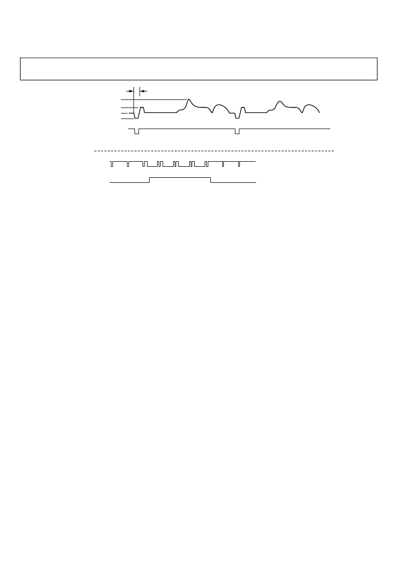
Figure 9. Sync Slicer and Sync Separator Output
Sync Separator
As part of sync processing, the sync separator’s task is to extract
Vsync from the composite sync signal. It works on the idea that
the Vsync signal stays active for a much longer time than the
Hsync signal. By using a digital low-pass filter and a digital
comparator, it rejects pulses with small durations (such as
Hsyncs and equalization pulses) and only passes pulses with
large durations, such as Vsync (see Figure 9).
The threshold of the digital comparator is programmable for
maximum flexibility. To program the threshold duration, write a
value (N) to Register 0x11. The resulting pulse width will be
N × 200 ns. So, if N = 5 the digital comparator threshold will be
1 μs. Any pulses less than 1 μs are rejected, while any pulse
greater than 1 μs passes through.
There are two things to keep in mind when using the sync
separator. First, the resulting clean Vsync output will be delayed
from the original Vsync by a duration equal to the digital
comparator threshold (N × 200 ns). Second, there is some
variability to the 200 ns multiplier value. The maximum varia-
bility over all operating conditions will be ±20% (160 ns to
240 ns). Since normal Vsync and Hsync pulse widths differ by a
factor of about 500 or more, the 20% variability is not an issue.
Hsync Filter and Regenerator
The Hsync filter is used to eliminate any extraneous pulses from
the Hsync or SOGIN inputs, outputting a clean, low-jitter signal
that is appropriate for mode detection and clock generation.
The Hsync regenerator is used to recreate a clean, although not
low jitter, Hsync signal that can be used for mode detection and
counting Hsyncs per Vsync. The Hsync regenerator has a high
degree of tolerance to extraneous and missing pulses on the
Hsync input, but is not appropriate for use by the PLL in
creating the pixel clock due to jitter.
The Hsync regenerator runs automatically and requires no
setup to operate. The Hsync filter requires the setting up of a
filter window. The filter window sets a periodic window of time
around the regenerated Hsync leading edge where valid Hsyncs
are allowed to occur. The general idea is that extraneous pulses
on the sync input will occur outside of this filter window and
thus will be filtered out. In order to set the filter window timing,
program a value (
x
) into Register 0x23. The resulting filter
window time is ±
x
times 25 ns around the regenerated Hsync
leading edge. Just as for the sync separator threshold multiplier,
allow a ±20% variance in the 25 ns multiplier to account for all
operating conditions (20 nS to 30 ns range).
A second output from the Hsync filter is a status bit (Reg-
ister 0x25, Bit 1) that tells whether extraneous pulses are present
on the incoming sync signal. Extraneous pulses are often
included for copy protection purposes; this status bit can be
used to detect that.
The filtered Hsync (rather than the raw Hsync/SOGIN signal)
for pixel clock generation by the PLL is controlled by Reg-
ister 0x20, Bit 2. The regenerated Hsync (rather than the raw
Hsync/ SOGIN signal) for the sync processing is controlled by
Register 0x20, Bit 1. Use of the filtered Hsync and regenerated
Hsync is recommended. See Figure 10 for an illustration of a
filtered Hsync.
相關(guān)PDF資料 |
PDF描述 |
|---|---|
| AD9980PCB | High Performance 8-Bit Display Interface |
| AD9994 | 12-Bit CCD Signal Processor with Precision Timing Generator |
| ADA10000S3C | Linear Amplifier MMIC |
| ADA10000 | Linear Amplifier MMIC Data Sheet - Rev 2.3 |
| ADA10000S24Q1 | Linear Amplifier MMIC Data Sheet - Rev 2.3 |
相關(guān)代理商/技術(shù)參數(shù) |
參數(shù)描述 |
|---|---|
| AD9980KSTZ-RL95 | 制造商:Analog Devices 功能描述: |
| AD9980PCB | 制造商:AD 制造商全稱:Analog Devices 功能描述:High Performance 8-Bit Display Interface |
| AD9981 | 制造商:AD 制造商全稱:Analog Devices 功能描述:High Performance 10-Bit Display Interface |
| AD9981/PCB | 制造商:AD 制造商全稱:Analog Devices 功能描述:High Performance 10-Bit Display Interface |
| AD9981/PCBZ | 制造商:Analog Devices 功能描述:Evaluation Board For The High Performance 10-Bit Display Interface 制造商:Analog Devices 功能描述:EVAL BD FOR THE HI-PERF 10-BIT DISPLAY INTRFC - Bulk |
發(fā)布緊急采購,3分鐘左右您將得到回復(fù)。