- 您現(xiàn)在的位置:買賣IC網(wǎng) > PDF目錄373959 > AD9101 (Analog Devices, Inc.) 125 MSPS Monolithic Sampling Amplifier(125MSPS單片采樣放大器) PDF資料下載
參數(shù)資料
| 型號: | AD9101 |
| 廠商: | Analog Devices, Inc. |
| 英文描述: | 125 MSPS Monolithic Sampling Amplifier(125MSPS單片采樣放大器) |
| 中文描述: | 125 MSPS的采樣單片放大器(125MSPS單片采樣放大器) |
| 文件頁數(shù): | 8/12頁 |
| 文件大?。?/td> | 213K |
| 代理商: | AD9101 |
AD9101
–8–
REV. 0
Deglitcher
Many recently announced video-speed digital-to-analog con-
verters feature very low glitch impulse. T his is the result of de-
sign emphasis on spurious free dynamic range (SFDR), a key
spec for the emerging direct digital synthesis (DDS) market.
T hese DACs have extremely low spurs and often do not require
deglitching.
Although their specs are impressive, these DACs may suffer har-
monic distortion, especially at higher clock rates. T herefore, a
deglitcher using the AD9101 can improve SFDR in some cases.
Figure 7 illustrates the block diagram for deglitching an
AD9713, 12-bit DAC.
SAMPLING
AMPLIFIER
(AD9101)
LOW
DISTORTION
OUTPUT
12
DAC
(AD9713)
DDS
ACCUMULATOR
(AD9955)
CLK1
CLK2
CLK3
32
TUNING
WORD
Figure 7. Deglitcher Block Diagram
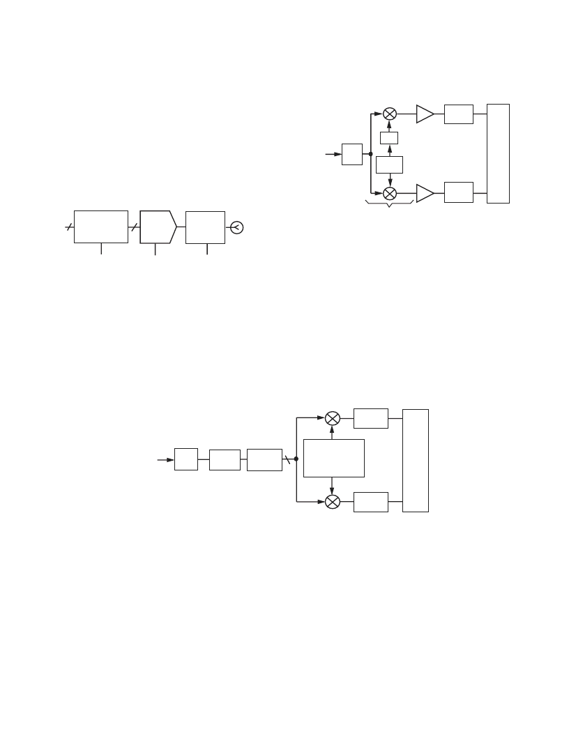
IF-to-Digital Conversion
T raditional receivers with information encoded with in phase (I)
and quadrature (Q) signals comprise extensive analog signal
processing ahead of the pair of ADCs.
T his I-Q demodulation in the analog domain requires precise
gain and phase matching as well as close matching of the ADCs.
T his leads to high cost both in materials and labor to attain the
desired performance. Digital front end designers have paid the
cost for these components because ADCs have limited the dy-
namic range at higher signal frequencies.
IF
BPF
DSP
I
Q
NUMERICALLY
CONTROLLED
OSCILLATOR
(NCO)
D
F
ADC
ANALOG
INPUT
H (z)
H (z)
12
AD9101
Figure 9. Direct IF-to-Digital
T hus, the final IF signal was mixed with quadrature signals
from the final LO. T he two resultant baseband signals repre-
senting I and Q were digitized by independent converters.
IF
BPF
QUADRATURE
DEMODULATOR
M
W
B
A
90°
LOCAL
OSC.
ADC
ADC
DSP
I
Q
ANALOG
INPUT
Figure 8. Traditional l-Q Demodulation
T his method, shown in block form in Figure 8, relies heavily on
accuracy of the phase of the analog I and Q signals applied to
the ADCs. As little as 0.5
°
of phase error can reduce system dy-
namic range by 6 dB or more.
Using the bandwidth and low distortion of the AD9101 greatly
simplifies the analog front end and allows signal processing to
be done in the digital domain which is more predictable and less
susceptible to environmental changes. T he simplified front end
is illustrated in Figure 9.
T his configuration removes the burden from the analog section.
T he AD9101 expands the dynamic range of the ADC into the
IF bandwidth, allowing straightforward digital algorithms to de-
modulate the I and Q data.
相關(guān)PDF資料 |
PDF描述 |
|---|---|
| AD9200KST | Complete 10-Bit, 20 MSPS, 80 mW CMOS A/D Converter |
| AD9200LQFP-EVAL | Complete 10-Bit, 20 MSPS, 80 mW CMOS A/D Converter |
| AD9200JRSRL | Complete 10-Bit, 20 MSPS, 80 mW CMOS A/D Converter |
| AD9200ARSRL | Complete 10-Bit, 20 MSPS, 80 mW CMOS A/D Converter |
| AD9200 | Complete 10-Bit, 20 MSPS, 80 mW CMOS A/D Converter |
相關(guān)代理商/技術(shù)參數(shù) |
參數(shù)描述 |
|---|---|
| AD9101AE | 制造商:AD 制造商全稱:Analog Devices 功能描述:125 MSPS Monolithic Sampling Amplifier |
| AD9101AR | 制造商:Analog Devices 功能描述: |
| AD9101AR-REEL | 制造商:Analog Devices 功能描述:SAMPLE AND HOLD 1CH 0.016US 20SOIC W - Tape and Reel |
| AD9101ARZ | 制造商:Analog Devices 功能描述:- Bulk |
| AD9101SE | 制造商:AD 制造商全稱:Analog Devices 功能描述:125 MSPS Monolithic Sampling Amplifier |
發(fā)布緊急采購,3分鐘左右您將得到回復(fù)。