- 您現(xiàn)在的位置:買賣IC網(wǎng) > PDF目錄375243 > AD8200YCSURF (ANALOG DEVICES INC) High Common-Mode Voltage, Single-Supply Difference Amplifier PDF資料下載
參數(shù)資料
| 型號: | AD8200YCSURF |
| 廠商: | ANALOG DEVICES INC |
| 元件分類: | 運動控制電子 |
| 英文描述: | High Common-Mode Voltage, Single-Supply Difference Amplifier |
| 中文描述: | OP-AMP, 1000 uV OFFSET-MAX, UUC7 |
| 封裝: | DIE-7 |
| 文件頁數(shù): | 7/12頁 |
| 文件大小: | 231K |
| 代理商: | AD8200YCSURF |
REV. B
AD8200
–7–
Internal Signal Overload Considerations
When configuring gain for values other than 20, the maximum
input voltage with respect to the supply voltage and ground
must be considered, since either the preamplifier or the output
buffer will reach its full-scale output (approximately
V
S
– 0.2
V
)
with large differential input voltages. The input of the AD8200
is limited to (
V
S
– 0.2)
÷
10, for overall gains
≤
10, since the
preamplifier, with its fixed gain of
×
10, reaches its full-scale
output before the output buffer. For gains greater than 10, the
swing at the buffer output reaches its full scale first and limits
the AD8200 input to (
V
S
– 0.2)
÷
G
, where
G
is the overall gain.
LOW-PASS FILTERING
In many transducer applications, it is necessary to filter the
signal to remove spurious high frequency components, including
noise, or to extract the mean value of a fluctuating signal with a
peak-to-average ratio (PAR) greater than unity. For example, a
full-wave rectified sinusoid has a PAR of 1.57, a raised cosine
has a PAR of 2, and a half-wave sinusoid has a PAR of 3.14.
Signals having large spikes may have PARs of 10 or more.
When implementing a filter, the PAR should be considered so
the output of the AD8200 preamplifier (A1) does not clip before
A2, since this nonlinearity would be averaged and appear as an
error at the output. To avoid this error, both amplifiers should
be made to clip at the same time. This condition is achieved
when the PAR is no greater than the gain of the second ampli-
fier (2 for the default configuration). For example, if a PAR of 5
is expected, the gain of A2 should be increased to 5.
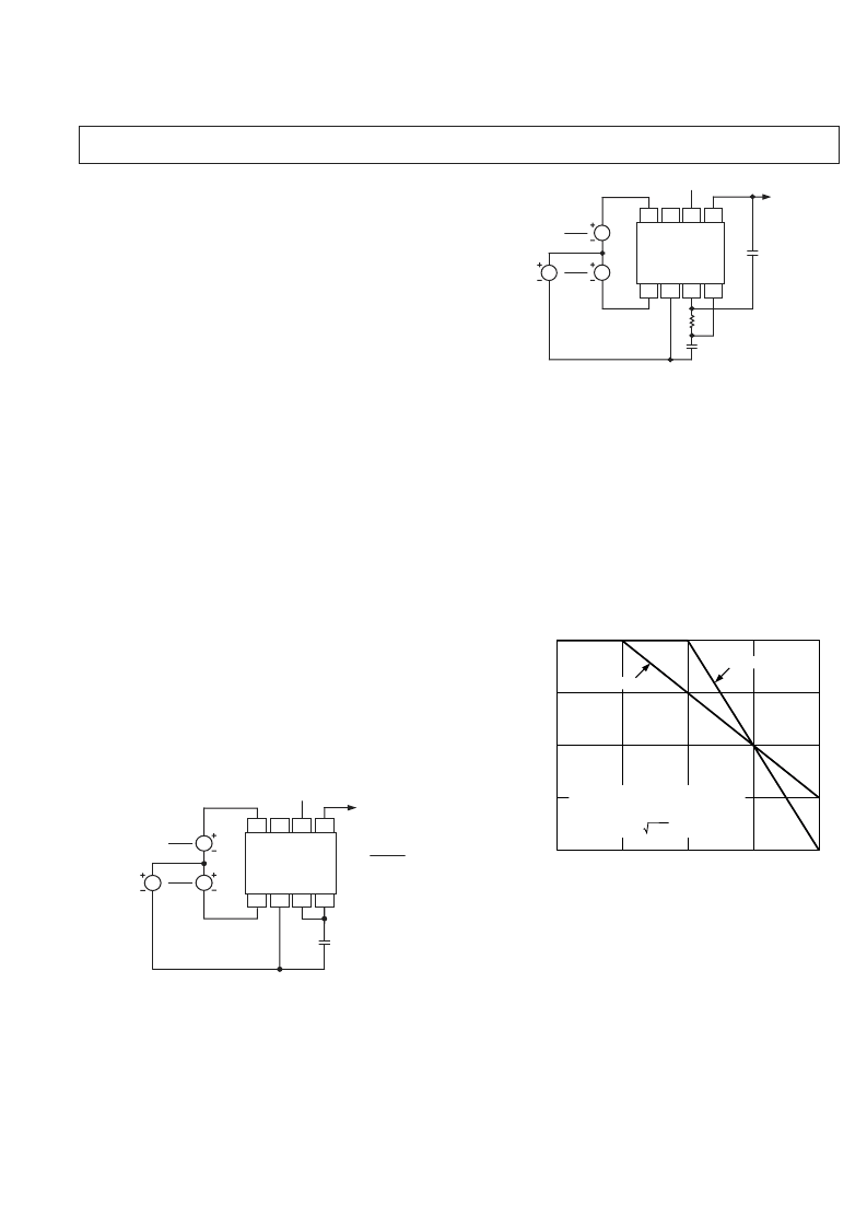
Low-pass filters can be implemented in several ways using the
features provided by the AD8200. In the simplest case, a single-
pole filter (20 dB/decade) is formed when the output of A1 is
connected to the input of A2 via the internal 100 k
resistor by
strapping Pins 3 and 4 and a capacitor added from this node to
ground, as shown in Figure 8. If a resistor is added across the
capacitor to lower the gain, the corner frequency will increase; it
should be calculated using the parallel sum of the resistor and
100 k
.
5V
C
V
CM
OUT
F
C
=
1
2 C10
5
C IN FARADS
V
DIFF
2
V
DIFF
2
NC = NO CONNECT
GND
NC
–IN
+IN
A1
+V
S
A2
OUT
AD8200
Figure 8. A Single-Pole, Low-Pass Filter Using the
Internal 100 k
Resistor
If the gain is raised using a resistor, as shown in Figure 8, the
corner frequency is lowered by the same factor as the gain is
raised. Thus, using a resistor of 200 k
(for which the gain
would be doubled), the corner frequency is now 0.796 Hz-
μ
F,
(0.039
μ
F for a 20 Hz corner frequency.)
OUT
V
CM
C
255k
C
F
C
= 1Hz – F
5V
NC = NO CONNECT
V
DIFF
2
V
DIFF
GND
NC
–IN
+IN
A1
+V
S
A2
OUT
AD8200
Figure 9. 2-Pole Low-Pass Filter
A 2-pole filter (with a roll-off of 40 dB/decade) can be implemented
using the connections shown in Figure 9. This is a Sallen-Key
form based on a
×
2 amplifier. It is useful to remember that a 2-pole
filter with a corner frequency f
2
and a 1-pole filter with a corner
at f
1
have the same attenuation at the frequency (f
22
/f
1
). The
attenuation at that frequency is 40 log (f
2
/f
1
). This is illustrated
in Figure 10. Using the standard resistor value shown and equal
capacitors (Figure 9), the corner frequency is conveniently scaled at
1 Hz-
μ
F (0.05
μ
F for a 20 Hz corner). A maximally flat response
occurs when the resistor is lowered to 196 k
and the scaling is
then 1.145 Hz-
μ
F. The output offset is raised by approximately
5 mV (equivalent to 250 V at the input pins).
40LOG (f
2
/f
1
)
f
1
A
f
2
f
22
/f
1
FREQUENCY
A 1-POLE FILTER, CORNER f
1
, AND
A 2-POLE FILTER, CORNER f
, HAVE
THE SAME ATTENUATION –40LOG (f
2
/f
1
)
AT FREQUENCY f
22
/f
1
20dB/DECADE
40dB/DECADE
Figure 10. Comparative Responses of 1-Pole and
2-Pole Low-Pass Filters
相關(guān)PDF資料 |
PDF描述 |
|---|---|
| AD8206YCSURF | Single-Supply 42 V System Difference Amplifier |
| AD8206YR | Single-Supply 42 V System Difference Amplifier |
| AD8206YR-REEL | Single-Supply 42 V System Difference Amplifier |
| AD8206YR-REEL7 | Single-Supply 42 V System Difference Amplifier |
| AD823 | Dual, 16 MHz, Rail-to-Rail FET Input Amplifier(16MHz,滿幅度,場效應(yīng)晶體管輸入雙運放) |
相關(guān)代理商/技術(shù)參數(shù) |
參數(shù)描述 |
|---|---|
| AD8200YR | 制造商:Analog Devices 功能描述:AMP DIFF SINGLE SUPPLY SMD 8200 |
| AD8200YR-REEL | 制造商:Analog Devices 功能描述:SP Amp Difference Amplifier Dual 12V 8-Pin SOIC N T/R |
| AD8200YR-REEL7 | 制造商:Analog Devices 功能描述:SP Amp Difference Amplifier Dual 12V 8-Pin SOIC N T/R |
| AD8200YR-REEL-7 | 制造商:未知廠家 制造商全稱:未知廠家 功能描述:Amplifier. Other |
| AD8202 | 制造商:AD 制造商全稱:Analog Devices 功能描述:Dual-Channel Audio Difference Amplifier |
發(fā)布緊急采購,3分鐘左右您將得到回復(fù)。