- 您現(xiàn)在的位置:買賣IC網(wǎng) > PDF目錄375232 > AD5227BUJZ50-RL72 (Analog Devices, Inc.) 64-Position Up/Down Control Digital Potentiometer PDF資料下載
參數(shù)資料
| 型號: | AD5227BUJZ50-RL72 |
| 廠商: | Analog Devices, Inc. |
| 元件分類: | 數(shù)字電位計 |
| 英文描述: | 64-Position Up/Down Control Digital Potentiometer |
| 中文描述: | 64工位上/下控制數(shù)字電位器 |
| 文件頁數(shù): | 10/16頁 |
| 文件大?。?/td> | 331K |
| 代理商: | AD5227BUJZ50-RL72 |
AD5227
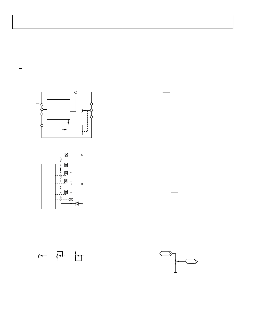
THEORY OF OPERATION
The AD5227 is a 64-position 3-terminal digitally controlled
potentiometer device. It presets to a midscale at system power-
on. When CS is enabled, changing the resistance settings is
achieved by clocking the CLK pin. It is negative-edge triggered,
and the direction of stepping is determined by the state of the
U/D input. When the wiper reaches the maximum or the
minimum setting, additional CLK pulses do not change the
wiper setting.
Rev. 0 | Page 10 of 16
0
CS
U/D
CLK
GND
V
DD
6-BIT UP/DOWN
CONTROL
LOGIC
POR
MIDSCALE
WIPER
REGISTER
A
W
B
AD5227
Figure 24. Functional Block Diagram
0
B
W
A
D0
D1
D2
D3
D4
D5
R
S
R
S
=
R
AB
/64
R
W
R
S
R
S
R
S
RDAC
UP/DOWN
CTRL AND
DECODE
Figure 25. AD5227 Equivalent RDAC Circuit
PROGRAMMING THE DIGITAL POTENTIOMETERS
Rheostat Operation
If only the W-to-B or W-to-A terminals are used as variable
resistors, the unused terminal can be opened or shorted with W.
This operation is called
rheostat mode
and is shown in Figure 26.
0
A
W
B
A
W
B
A
W
B
Figure 26. Rheostat Mode Configuration
The end-to-end resistance, R
AB
, has 64 contact points accessed
by the wiper terminal, plus the B terminal contact, assuming
that R
WB
is used (see Figure 25). Clocking the CLK input steps,
R
WB
by one step. The direction is determined by the state of U/D
WB
can be determined by the number of
clock pulses, provided that the AD5227 has not reached its
maximum or minimum scale.
R
WB
can, therefore, be
approximated as
+
×
±
=
W
AB
64
WB
R
R
R
CP
(1)
where:
CP
is the number of clock pulses.
R
AB
is the end-to-end resistance.
R
W
is the wiper resistance contributed by the on-resistance of
the internal switch.
Since in the lowest end of the resistor string a finite wiper
resistance is present, care should be taken to limit the current
flow between W and B in this state to a maximum pulse current
of no more than 20 mA. Otherwise, degradation or possible
destruction of the internal switches can occur.
Similar to the mechanical potentiometer, the resistance of the
RDAC between the Wiper W and Terminal A also produces a
digitally controlled complementary resistance, R
WA
. When these
terminals are used, the B terminal can be opened or shorted to
W. Similarly, R
WA
can be approximated as
(
)
+
±
=
W
AB
64
WA
R
R
R
CP
64
(2)
Equations 1 and 2 do not apply when CP = 0.
The typical distribution of the resistance tolerance from device
to device is process lot dependent. It is possible to have ±20%
tolerance.
Potentiometer Mode Operation
If all three terminals are used, the operation is called
potentiometer mode.
The most common configuration is the
voltage divider operation as shown in Figure 27.
0
A
W
B
V
I
V
C
Figure 27. Potentiometer Mode Configuration
相關(guān)PDF資料 |
PDF描述 |
|---|---|
| AD5227EVAL | 64-Position Up/Down Control Digital Potentiometer |
| AD5243 | Dual 256-Position I2C Compatible Digital Potentiometer |
| AD5243BRM10 | Dual 256-Position I2C Compatible Digital Potentiometer |
| AD5243BRM100 | Dual 256-Position I2C Compatible Digital Potentiometer |
| AD5243BRM100-RL7 | Dual 256-Position I2C Compatible Digital Potentiometer |
相關(guān)代理商/技術(shù)參數(shù) |
參數(shù)描述 |
|---|---|
| AD5227EVAL | 制造商:AD 制造商全稱:Analog Devices 功能描述:64-Position Up/Down Control Digital Potentiometer |
| AD5228 | 制造商:AD 制造商全稱:Analog Devices 功能描述:32-Position Manual Up/Down Control Potentiometer |
| AD5228BUJZ10 | 制造商:Analog Devices 功能描述:DGTL POTENTIOMETER 32POS 10KOHM SGL 8PIN TSOT - Bulk |
| AD5228BUJZ100 | 制造商:Analog Devices 功能描述:DGTL POTENTIOMETER 32POS 100KOHM SGL 8PIN TSOT - Bulk |
| AD5228BUJZ1002-R2 | 制造商:AD 制造商全稱:Analog Devices 功能描述:32-Position Manual Up/Down Control Potentiometer |
發(fā)布緊急采購,3分鐘左右您將得到回復(fù)。