- 您現(xiàn)在的位置:買(mǎi)賣(mài)IC網(wǎng) > PDF目錄375222 > AAT3682 (Advanced Analogic Technologies, Inc.) Lithium-Ion/Polymer Linear Battery Charger PDF資料下載
參數(shù)資料
| 型號(hào): | AAT3682 |
| 廠商: | Advanced Analogic Technologies, Inc. |
| 英文描述: | Lithium-Ion/Polymer Linear Battery Charger |
| 中文描述: | 鋰離子線性電池充電器 |
| 文件頁(yè)數(shù): | 13/18頁(yè) |
| 文件大?。?/td> | 233K |
| 代理商: | AAT3682 |
第1頁(yè)第2頁(yè)第3頁(yè)第4頁(yè)第5頁(yè)第6頁(yè)第7頁(yè)第8頁(yè)第9頁(yè)第10頁(yè)第11頁(yè)第12頁(yè)當(dāng)前第13頁(yè)第14頁(yè)第15頁(yè)第16頁(yè)第17頁(yè)第18頁(yè)
Protection Circuitry
The AAT3682 is a highly integrated battery manage-
ment system IC including several protection fea-
tures. In addition to battery temperature monitoring,
the IC constantly monitors for over-current and over-
voltage conditions; if an over-current situation
occurs, the AAT3682 latches off the pass device to
prevent damage to the battery or the system, and
enters shutdown mode until the over-current event is
terminated. An over-voltage condition is defined as a
condition where the voltage on the BAT pin exceeds
the maximum battery charge voltage. If an over-volt-
age condition occurs, the IC turns off the pass
device until voltage on the BAT pin drops below the
maximum battery charge constant voltage threshold.
The AAT3682 will resume normal operation after the
over-current or over-voltage condition is removed.
During an over-current or over-voltage event, the
STAT will report a FAULT signal. In the event of a
battery over-temperature condition, the IC will turn
off the pass device and report a FAULT signal on the
STAT pin. After the system recovers from a temper-
ature fault, the IC will resume operation in the 1X
trickle charge mode to prevent damage to the sys-
tem in the event a defective battery is placed under
charge. Once the battery voltage rises above the
trickle charge to constant current charge threshold,
the IC will resume the constant current mode.
Applications Information
Choosing a Sense Resistor
The charging rate recommended by Lithium-Ion
cell vendors is normally 1C, with a 2C absolute
maximum rating. Charging at the highest recom-
mended rate offers the advantage of shortened
charging time without decreasing the battery's lifes-
pan. This means that the suggested fast charge
rate for a 500mAH battery pack is 500mA. Refer to
the Safe Operating Area curves in the Typical
Characteristics section of this datasheet to deter-
mine the maximum allowable charge current for a
given input voltage. The current sense resistor,
R
SENSE
, programs the charge current according to
the following equation:
Where I
CHARGE
is the desired typical charge current
during constant-current charge mode. V
CC
- V
CSI
is
the voltage across R
SENSE
, shown in the Electrical
Characteristic table as V
CS
. To program a nominal
500mA charge current during fast-charge, a
200m
value resistor should be selected.
V
- V
CHARGE
R
SENSE
= I
AAT3682
Lithium-Ion/Polymer Linear Battery Charger
3682.2005.02.1.1
13
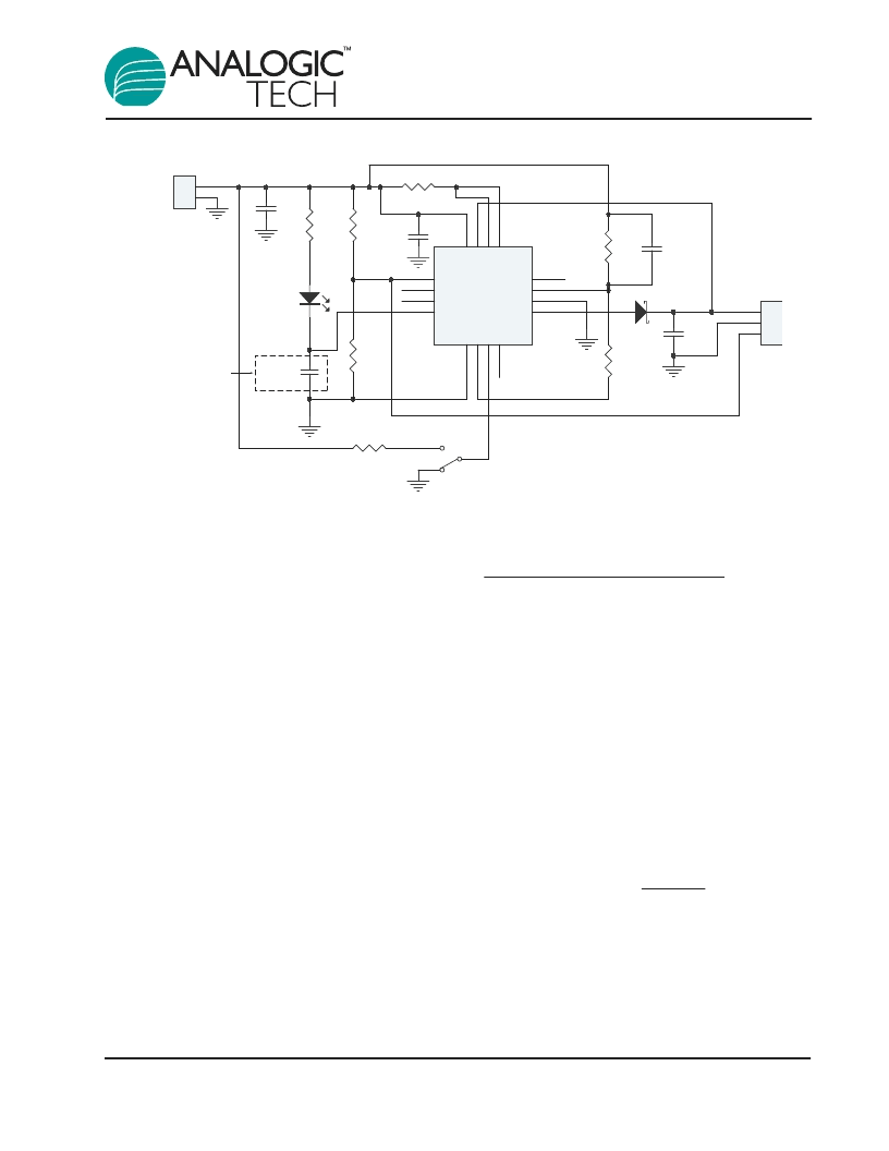
Figure 5: Evaluation Board Schematic.
1
2
J1
GND
1
2
3
J2
1K
R4
0.2
R2
1K
R3
2.2K
R1
100K
R6
100K
R5
D2
22
μ
F
C1
10
μ
F
C2
Green LED
V
IN
D1
47nF
C3
TS
N/C
N/C
STAT
1
2
3
4
V
5
D
6
T
7
N
8
BAT
9
10
VSS
11
N/C
12
V
1
C
1
B
1
V
1
AAT3682
U1
100K
R7
2
1
3
SW-T2X
S1
1000pF
C4
4.7
μ
F
C5
Remove capacitor for
progressive dimming
相關(guān)PDF資料 |
PDF描述 |
|---|---|
| AAT3682ISN-4.2-T1 | Lithium-Ion/Polymer Linear Battery Charger |
| AAT4250IGV-T1 | Slew Rate Controlled Load Switch |
| AAT4250 | Slew Rate Controlled Load Switch |
| AAT4250IJS-T1 | Slew Rate Controlled Load Switch |
| AAT4280IJS-1-T1 | Slew Rate Controlled Load Switch |
相關(guān)代理商/技術(shù)參數(shù) |
參數(shù)描述 |
|---|---|
| AAT3683IOQ-4.2-2-DB1 | 制造商:Skyworks Solutions Inc 功能描述:AAT3683 Series 1 A Linear Li-Ion Battery Charger Evaluation Board |
| AAT3683IOQ-4.2-2-T1 | 制造商:Skyworks Solutions Inc 功能描述:IC BATT CHARGER 1A LI ION 制造商:Skyworks Solutions Inc 功能描述:POWER MANAGEMENT IC |
| AAT3683IOQ-4.2-3-T1 | 制造商:Skyworks Solutions Inc 功能描述:AAT3683 Series 7.5 V 1 A Linear Li-Ion Battery Charger - STDFN-10 |
| AAT3683IVN-4.2-4-T1 | 制造商:Skyworks Solutions Inc 功能描述:POWER MANAGEMENT IC |
| AAT3684IOQ-4.2-1-T1 | 制造商:Skyworks Solutions Inc 功能描述:AAT3684 Series 6.5V 500mA Lithium-Ion / Polymer Battery Charger -STDFN2.2x2.2-10 |
發(fā)布緊急采購(gòu),3分鐘左右您將得到回復(fù)。