- 您現(xiàn)在的位置:買(mǎi)賣(mài)IC網(wǎng) > PDF目錄63954 > AA038N2-00 (SKYWORKS SOLUTIONS INC) 28000 MHz - 40000 MHz RF/MICROWAVE WIDE BAND LOW POWER AMPLIFIER PDF資料下載
參數(shù)資料
| 型號(hào): | AA038N2-00 |
| 廠商: | SKYWORKS SOLUTIONS INC |
| 元件分類(lèi): | 放大器 |
| 英文描述: | 28000 MHz - 40000 MHz RF/MICROWAVE WIDE BAND LOW POWER AMPLIFIER |
| 封裝: | DIE |
| 文件頁(yè)數(shù): | 1/3頁(yè) |
| 文件大小: | 153K |
| 代理商: | AA038N2-00 |
Skyworks Solutions, Inc. [978] 241-7000
Fax [978] 241-7906 Email sales@skyworksinc.com www.skyworksinc.com
1
Specifications subject to change without notice. 11/02A
28–40 GHz GaAs MMIC
Low Noise Amplifier
Features
■ Single Bias Supply Operation (4.5 V)
■ 3.8 dB Typical Noise Figure at 38 GHz
■ 17 dB Typical Small Signal Gain
■ 0.25 m Ti/Pd/Au Gates
■ 100% On-Wafer RF, DC and Noise Figure
Testing
■ 100% Visual Inspection to MIL-STD-883
MT 2010
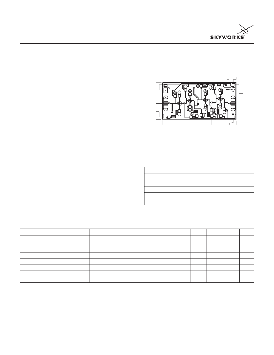
Chip Outline
AA038N1-00, AA038N2-00
Description
Skyworks’ four-stage reactively-matched 28–40 GHz
GaAs MMIC low noise amplifier has typical small signal
gain of 17 dB with a typical noise figure of 3.8 dB at 38
GHz. The chip uses Skyworks’ proven 0.25
m low noise
PHEMT technology, and is based upon MBE layers and
electron beam lithography for the highest uniformity and
repeatability. The FETs employ surface passivation to
ensure a rugged, reliable part with through-substrate via
holes and gold-based backside metallization to facilitate
a conductive epoxy die attach process.
Parameter
Condition
Symbol
Min.
Typ.3
Max.
Unit
Drain Current
IDS
35
50
mA
Small Signal Gain
F = 28–40 GHz
G
15
17
dB
Noise Figure
F = 38 GHz
NF
3.8
4.2
dB
Input Return Loss
F = 28–40 GHz
RLI
-10
-6
dB
Output Return Loss
F = 28–40 GHz
RLO
-8
-6
dB
Output Power at 1 dB Gain Compression1
F = 38 GHz
P1 dB
6
dBm
Two-Tone Output Third-Order Intercept1
F = 38 GHz
OIP3
15
dBm
Thermal Resistance2
ΘJC
101
°C/W
Electrical Specifications at 25°C (VDS = 4.5 V)
AA038N1-00
0.000
0.588
0.246
1.264
1.813
2.146
2.710
2.600
0.087
0.124
1.355
1.560
1.961
2.183
2.445
2.599
1.267
1.274
Dimensions indicated in mm.
All DC (V) pads are 0.1 x 0.1 mm and RF In, Out pads are 0.07 mm wide.
Chip thickness = 0.1 mm.
Characteristic
Value
Operating Temperature (TC)
-55°C to +90°C
Storage Temperature (TST)
-65°C to +150°C
Bias Voltage (VD)6 VDC
Power In (PIN)
10 dBm
Junction Temperature (TJ)
175°C
Absolute Maximum Ratings
1. Not measured on a 100% basis.
2. Calculated value based on measurement of discrete FET.
3. Typical represents the median parameter value across the specified
frequency range for the median chip.
相關(guān)PDF資料 |
PDF描述 |
|---|---|
| AA038P3-00 | 37000 MHz - 42000 MHz RF/MICROWAVE WIDE BAND LOW POWER AMPLIFIER |
| AA038P3-00 | 37000 MHz - 42000 MHz RF/MICROWAVE WIDE BAND LOW POWER AMPLIFIER |
| AA101-80 | 500 MHz - 2500 MHz RF/MICROWAVE VARIABLE ATTENUATOR, 3.3 dB INSERTION LOSS-MAX |
| AA110-85 | 0 MHz - 2000 MHz RF/MICROWAVE VARIABLE ATTENUATOR, 2.6 dB INSERTION LOSS-MAX |
| AA1L3N | 100 mA, 50 V, NPN, Si, SMALL SIGNAL TRANSISTOR, TO-92 |
相關(guān)代理商/技術(shù)參數(shù) |
參數(shù)描述 |
|---|---|
| AA038P1-00 | 制造商:SKYWORKS 制造商全稱(chēng):SKYWORKS 功能描述:36-39 GHz GaAs MMIC Driver Amplifier |
| AA038P2-00 | 制造商:ALPHA 制造商全稱(chēng):ALPHA 功能描述:37-40 GHz GaAs MMIC Driver Amplifier |
| AA038P5-00 | 制造商:ALPHA 制造商全稱(chēng):ALPHA 功能描述:37-39 GHz GaAs MMIC Power Amplifier |
| AA03A | 制造商:未知廠家 制造商全稱(chēng):未知廠家 功能描述:Analog IC |
| AA03A-005L-050S | 制造商:Emerson Network Power 功能描述: |
發(fā)布緊急采購(gòu),3分鐘左右您將得到回復(fù)。