- 您現(xiàn)在的位置:買賣IC網(wǎng) > PDF目錄375100 > A1204 (Allegro MicroSystems, Inc.) Continuous-Time Bipolar Switch Family PDF資料下載
參數(shù)資料
| 型號(hào): | A1204 |
| 廠商: | Allegro MicroSystems, Inc. |
| 英文描述: | Continuous-Time Bipolar Switch Family |
| 中文描述: | 連續(xù)時(shí)間雙極開關(guān)系列 |
| 文件頁(yè)數(shù): | 3/13頁(yè) |
| 文件大?。?/td> | 455K |
| 代理商: | A1204 |
第1頁(yè)第2頁(yè)當(dāng)前第3頁(yè)第4頁(yè)第5頁(yè)第6頁(yè)第7頁(yè)第8頁(yè)第9頁(yè)第10頁(yè)第11頁(yè)第12頁(yè)第13頁(yè)
3
A1201-DS, Rev. 2
Worcester, Massachusetts 01615-0036 (508) 853-5000
www.allegromicro.com
115 Northeast Cutoff, Box 15036
Allegro MicroSystems, Inc.
Continuous-Time Bipolar Switch Family
A1201, A1202, A1203, and A1204
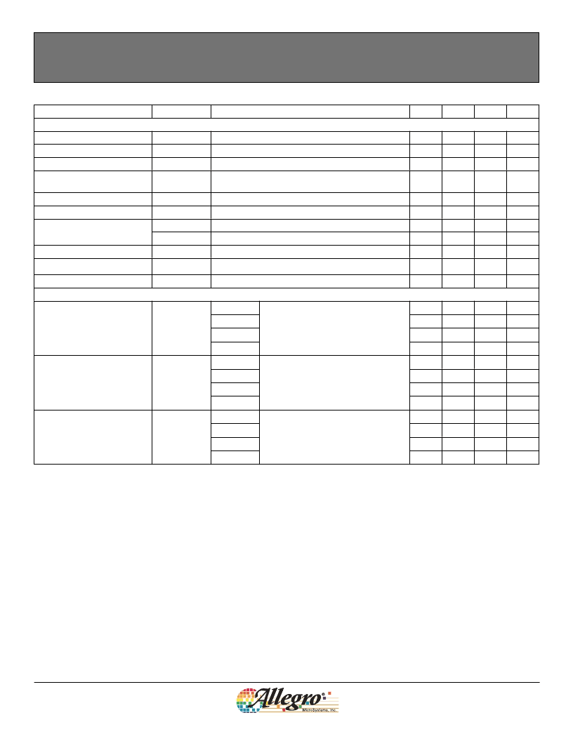
OPERATING CHARACTERISTICS
over full operating voltage and ambient temperature ranges, unless otherwise noted
Characteristic
Symbol
Electrical Characteristics
Supply Voltage
1
V
CC
Operating, T
J
< 165°C
Output Leakage Current
I
OUTOFF
V
OUT
= 24 V, B < B
RP
Output On Voltage
V
OUT(SAT)
I
OUT
= 20 mA, B > B
OP
Slew rate (dV
CC
/dt) < 2.5 V/μs, B > B
OP
+ 5 G or
B < B
RP
– 5 G
Output Rise Time
3
t
r
V
CC
= 12 V, R
LOAD
= 820
, C
S
= 12 pF
Output Fall Time
3
t
f
V
CC
= 12 V, R
LOAD
= 820
, C
S
= 12 pF
I
CCON
B > B
OP
I
CCOFF
B < B
RP
Reverse Battery Current
I
RCC
V
RCC
= –30 V
Supply Zener Clamp Voltage
V
Z
I
CC
= 10.5 mA; T
A
= 25°C
Supply Zener Current
4
I
Z
V
Z
= 32 V; T
A
= 25°C
Magnetic Characteristics
5
Test Conditions
Min.
Typ.
Max.
Units
3.8
–
–
–
–
24
10
400
V
μA
mV
215
Power-On Time
2
t
PO
–
–
4
μs
–
–
–
–
–
–
–
2
2
μs
μs
mA
mA
mA
Supply Current
3.8
3.5
–
7.5
7.5
–10
32
–
–
V
–
–
10.5
mA
Operate Point
B
OP
A1201
A1202
A1203
A1204
A1201
A1202
A1203
A1204
A1201
A1202
A1203
A1204
South pole adjacent to branded face
of device
–40
–
–
–100
–50
–75
–95
–150
5
30
30
50
15
26
26
42
–15
–26
–26
–40
30
52
52
82
50
75
95
150
40
–
–
100
55
–
–
115
G
G
G
G
Release Point
B
RP
North pole adjacent to branded face
of device
G
G
G
G
Hysteresis
B
HYS
B
OP
– B
RP
G
G
G
G
1
Maximum voltage must be adjusted for power dissipation and junction temperature, see
Power Derating
section.
2
For V
slew rates greater than 250 V/μs, and T
A
= 150°C, the Power-On Time can reach its maximum value.
3
C
=oscilloscope probe capacitance.
4
Maximum current limit is equal to the maximum I
+ 22 mA.
5
Magnetic flux density, B, is indicated as a negative value for north-polarity magnetic fields, and as a positive value for south-polarity magnetic fields.
This so-called algebraic convention supports arithmetic comparison of north and south polarity values, where the relative strength of the field is indicated
by the absolute value of B, and the sign indicates the polarity of the field (for example, a –100 G field and a 100 G field have equivalent strength, but
opposite polarity).
DEVICE QUALIFICATION PROGRAM
Contact Allegro for information.
EMC (Electromagnetic Compatibility) REQUIREMENTS
Contact Allegro for information.
相關(guān)PDF資料 |
PDF描述 |
|---|---|
| A1204EUA-T | Continuous-Time Bipolar Switch Family |
| A1204LLHLT-T | Continuous-Time Bipolar Switch Family |
| A1205 | Continuous-Time Bipolar Switch |
| A1205ELHLT-T | Continuous-Time Bipolar Switch |
| A1205EUA-T | Continuous-Time Bipolar Switch |
相關(guān)代理商/技術(shù)參數(shù) |
參數(shù)描述 |
|---|---|
| A1204 10HDG | 制造商:Thomas & Betts 功能描述:CHANNEL |
| A1204 20RW | 制造商:Thomas & Betts 功能描述:TWO A1202S WELDED TOGETHER |
| A1204.0 | 制造商:DORMER 功能描述:STUB DRILL HSS 4MM 制造商:DORMER 功能描述:STUB DRILL, HSS, 4MM 制造商:DORMER 功能描述:STUB DRILL, HSS, 4MM; Drill Bit Size Metric:4mm; Effective Length:22mm; Overall Length:55mm; SVHC:No SVHC (19-Dec-2012); Drill Bit Type:Stub; Drill Point Diameter:4mm; External Diameter:4.00mm; Material:HSS ;RoHS Compliant: NA |
| A1204.2 | 制造商:DORMER 功能描述:STUB DRILL HSS 4.2MM |
| A1204.5 | 制造商:DORMER 功能描述:STUB DRILL HSS 4.5MM |
發(fā)布緊急采購(gòu),3分鐘左右您將得到回復(fù)。