- 您現(xiàn)在的位置:買(mǎi)賣(mài)IC網(wǎng) > PDF目錄223002 > 7MBR25SC120 (FUJI ELECTRIC CO LTD) 39.25 A, 1600 V, SCR PDF資料下載
參數(shù)資料
| 型號(hào): | 7MBR25SC120 |
| 廠商: | FUJI ELECTRIC CO LTD |
| 元件分類(lèi): | 晶閘管 |
| 英文描述: | 39.25 A, 1600 V, SCR |
| 封裝: | MODULE-26 |
| 文件頁(yè)數(shù): | 2/7頁(yè) |
| 文件大小: | 420K |
| 代理商: | 7MBR25SC120 |
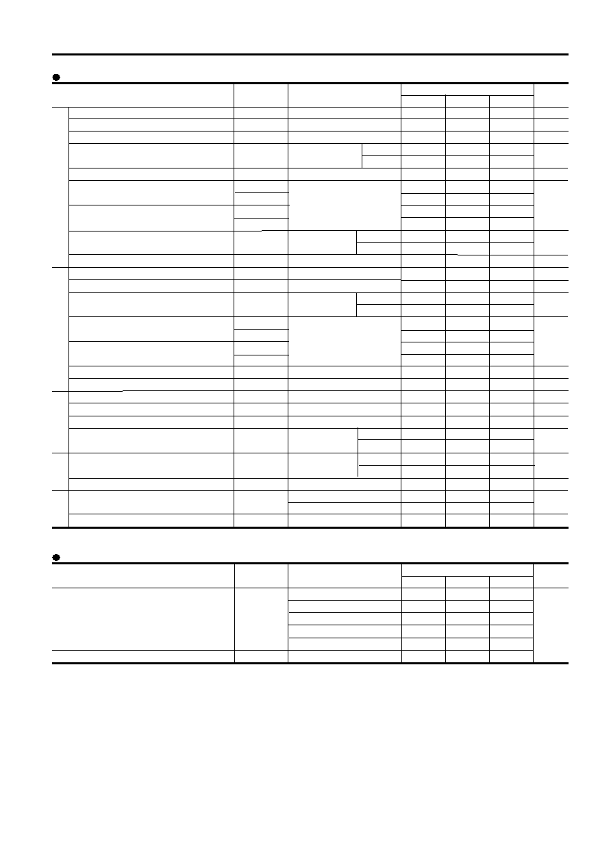
Electrical characteristics (Tj=25°C unless otherwise specified)
Item
Symbol
Condition
Characteristics
Unit
Min.
Typ.
Max.
Zero gate voltage collector current
Gate-Emitter leakage current
Gate-Emitter threshold voltage
Collector-Emitter saturation voltage
Input capacitance
Turn-on time
Turn-off
Forward on voltage
Reverse recovery time of FRD
Zero gate voltage collector current
Gate-Emitter leakage current
Collector-Emitter saturation voltage
Turn-on time
Turn-off time
Reverse current
off-state current
Reverse current
Gate trigger current
Gate trigger voltage
On-state voltage
Forward on voltage
Reverse current
Resistance
B value
Thermistor
Converter
Thyristor
Brake
Inverter
ICES
IGES
VGE(th)
VCE(sat)
Cies
ton
tr
toff
tf
VF
trr
ICES
IGES
VCE(sat)
ton
tr
toff
tf
IRRM
IDM
IRRM
IGT
VGT
VTM
VFM
IRRM
R
B
VCE=1200V, VGE=0V
VCE=0V, VGE=±20V
VCE=20V, IC=25mA
VGE=15V, Ic=25A
chip
terminal
VGE=0V, VCE=10V, f=1MHz
VCC=600V
IC=25A
VGE=±15V
RG=51
IF=25A
chip
terminal
IF=25A
VCES=1200V, VGE=0V
VCE=0V, VGE=±20V
IC=15A, VGE=15V chip
terminal
VCC=600V
IC=15A
VGE=±15V
RG=82
VR=1200V
VDM=1600V
VRM=1600V
VD=6V, IT=1A
ITM=25A
chip
terminal
IF=25A
chip
terminal
VR=1600V
T=25°C
T=100°C
T=25/50°C
100
200
8.5
2.6
1.2
0.6
1.0
0.3
3.2
350
100
200
2.6
1.2
0.6
1.0
0.3
100
1.0
100
2.5
1.15
1.5
100
3000
5.5
7.2
A
nA
V
pF
s
V
ns
A
nA
V
s
A
mA
V
A
K
Item
Symbol
Condition
Characteristics
Unit
Min.
Typ.
Max.
Inverter IGBT
Inverter FWD
Brake IGBT
Thyristor
Converter Diode
With thermal compound
0.69
1.30
1.14
1.00
°C/W
0.90
0.05
Thermal resistance ( 1 device )
Rth(j-c)
Contact thermal resistance
*
Rth(c-f)
Thermal resistance Characteristics
IGBT Module
7MBR25SC120
* This is the value which is defined mounting on the additional cooling fin with thermal compound
2.1
2.2
0.35
0.25
0.45
0.08
2.3
2.4
2.1
2.2
0.35
0.25
0.45
0.08
1.05
1.1
1.2
5000
465
495
520
3305
3375
3450
相關(guān)PDF資料 |
PDF描述 |
|---|---|
| 7MBR50SC060 | 78.5 A, 800 V, SCR |
| 7MBR50SD120 | 50 A, 1600 V, SCR |
| 7P002FLV2101I25 | 1M X 16 FLASH 3V PROM CARD, 250 ns, XMA68 |
| 7P004FLV2100I15 | 2M X 16 FLASH 3V PROM CARD, 150 ns, XMA68 |
| 7P008FLV2401I25 | 4M X 16 FLASH 3V PROM CARD, 250 ns, XMA68 |
相關(guān)代理商/技術(shù)參數(shù) |
參數(shù)描述 |
|---|---|
| 7MBR25SC-120 | 制造商:未知廠家 制造商全稱(chēng):未知廠家 功能描述:7 PIM IGBT |
| 7MBR25SC120_04 | 制造商:FUJI 制造商全稱(chēng):Fuji Electric 功能描述:PIM/Built-in converter with thyristor and brake |
| 7MBR25UA120 | 制造商:FUJI 制造商全稱(chēng):Fuji Electric 功能描述:IGBT MODULE (U series) 1200V / 25A / PIM |
| 7MBR25UA-120 | 制造商:未知廠家 制造商全稱(chēng):未知廠家 功能描述:IGBTs |
| 7MBR25UA-120-50 | 制造商:Fuji Electric 功能描述:IGBT 7 PACK MOD 1200V 25A M711 |
發(fā)布緊急采購(gòu),3分鐘左右您將得到回復(fù)。