- 您現(xiàn)在的位置:買賣IC網(wǎng) > PDF目錄369290 > 74AC299MTR (意法半導(dǎo)體) 8 BIT PIPO SHIFT REGISTER WITH ASYNCHRONOUS CLEAR PDF資料下載
參數(shù)資料
| 型號(hào): | 74AC299MTR |
| 廠商: | 意法半導(dǎo)體 |
| 元件分類: | 通用總線功能 |
| 英文描述: | 8 BIT PIPO SHIFT REGISTER WITH ASYNCHRONOUS CLEAR |
| 中文描述: | 8位皮普移位寄存器帶異步清零 |
| 文件頁數(shù): | 7/13頁 |
| 文件大?。?/td> | 465K |
| 代理商: | 74AC299MTR |
74AC299
7/13
CAPACITIVE CHARACTERISTICS
1) C
PD
is defined as the value of the IC’s internal equivalent capacitance which is calculated from the operating current consumption without
load. (Refer to Test Circuit). Average operating current can be obtained by the following equation. I
CC(opr)
= C
PD
x V
CC
x f
IN
+ I
CC
/n (per circuit)
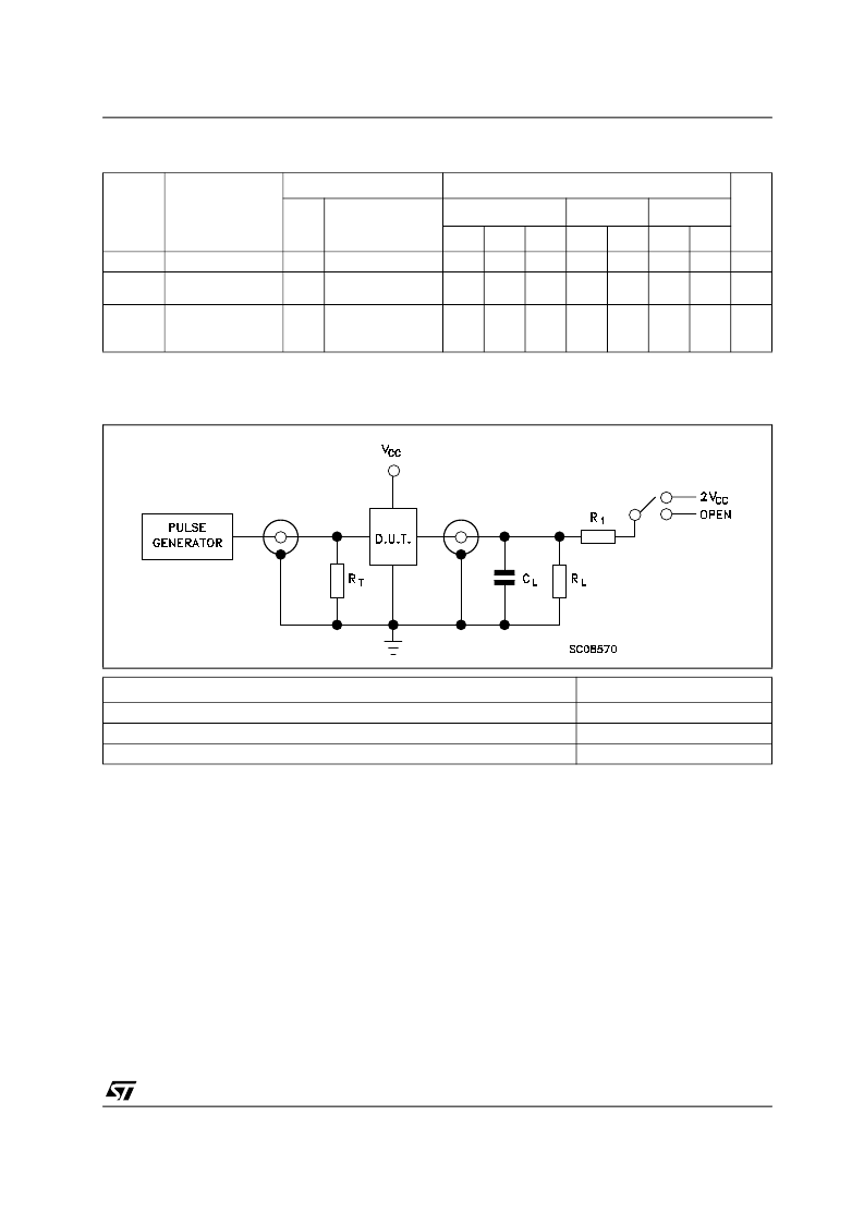
TEST CIRCUIT
C
L
= 50pF or equivalent (includes jig and probe capacitance)
R
L
= R
1
= 500
or equivalent
R
T
= Z
OUT
of pulse generator (typically 50
)
Symbol
Parameter
Test Condition
Value
Unit
V
CC
(V)
T
A
= 25°C
-40 to 85°C
-55 to 125°C
Min.
Typ.
Max.
Min.
Max.
Min.
Max.
C
IN
Input Capacitance
Bus Input
Capacitance
Power Dissipation
Capacitance (note
1)
5.0
5
10
10
pF
C
i/O
5.0
13
pF
C
PD
5.0
f
IN
= 10MHz
120
pF
TEST
SWITCH
t
PLH
, t
PHL
t
PZL
, t
PLZ
t
PZH
, t
PHZ
Open
2V
CC
Open
相關(guān)PDF資料 |
PDF描述 |
|---|---|
| 74AC299 | 8 BIT PIPO SHIFT REGISTER WITH ASYNCHRONOUS CLEAR |
| 74AC299B | 8 BIT PIPO SHIFT REGISTER WITH ASYNCHRONOUS CLEAR |
| 74AC299M | 8 BIT PIPO SHIFT REGISTER WITH ASYNCHRONOUS CLEAR |
| 74AC299PC | 8-Input Universal Shift/Storage Register |
| 74AC299MTC | 8-Input Universal Shift/Storage Register |
相關(guān)代理商/技術(shù)參數(shù) |
參數(shù)描述 |
|---|---|
| 74AC299PC | 功能描述:計(jì)數(shù)器移位寄存器 8-Inp Shift/Stor Reg RoHS:否 制造商:Texas Instruments 計(jì)數(shù)器類型: 計(jì)數(shù)順序:Serial to Serial/Parallel 電路數(shù)量:1 封裝 / 箱體:SOIC-20 Wide 邏輯系列: 邏輯類型: 輸入線路數(shù)量:1 輸出類型:Open Drain 傳播延遲時(shí)間:650 ns 最大工作溫度:+ 125 C 最小工作溫度:- 40 C 封裝:Reel |
| 74AC299PC_Q | 功能描述:計(jì)數(shù)器移位寄存器 8-Inp Shift/Stor Reg RoHS:否 制造商:Texas Instruments 計(jì)數(shù)器類型: 計(jì)數(shù)順序:Serial to Serial/Parallel 電路數(shù)量:1 封裝 / 箱體:SOIC-20 Wide 邏輯系列: 邏輯類型: 輸入線路數(shù)量:1 輸出類型:Open Drain 傳播延遲時(shí)間:650 ns 最大工作溫度:+ 125 C 最小工作溫度:- 40 C 封裝:Reel |
| 74AC299SC | 功能描述:計(jì)數(shù)器移位寄存器 8-Inp Shift/Stor Reg RoHS:否 制造商:Texas Instruments 計(jì)數(shù)器類型: 計(jì)數(shù)順序:Serial to Serial/Parallel 電路數(shù)量:1 封裝 / 箱體:SOIC-20 Wide 邏輯系列: 邏輯類型: 輸入線路數(shù)量:1 輸出類型:Open Drain 傳播延遲時(shí)間:650 ns 最大工作溫度:+ 125 C 最小工作溫度:- 40 C 封裝:Reel |
| 74AC299SCX | 功能描述:計(jì)數(shù)器移位寄存器 8-Inp Shift/Stor Reg RoHS:否 制造商:Texas Instruments 計(jì)數(shù)器類型: 計(jì)數(shù)順序:Serial to Serial/Parallel 電路數(shù)量:1 封裝 / 箱體:SOIC-20 Wide 邏輯系列: 邏輯類型: 輸入線路數(shù)量:1 輸出類型:Open Drain 傳播延遲時(shí)間:650 ns 最大工作溫度:+ 125 C 最小工作溫度:- 40 C 封裝:Reel |
| 74AC299SJ | 功能描述:計(jì)數(shù)器移位寄存器 8-Inp Shift/Stor Reg RoHS:否 制造商:Texas Instruments 計(jì)數(shù)器類型: 計(jì)數(shù)順序:Serial to Serial/Parallel 電路數(shù)量:1 封裝 / 箱體:SOIC-20 Wide 邏輯系列: 邏輯類型: 輸入線路數(shù)量:1 輸出類型:Open Drain 傳播延遲時(shí)間:650 ns 最大工作溫度:+ 125 C 最小工作溫度:- 40 C 封裝:Reel |
發(fā)布緊急采購,3分鐘左右您將得到回復(fù)。