- 您現(xiàn)在的位置:買賣IC網(wǎng) > PDF目錄92477 > 6VW1 (CORCOM INC) 120 V, 50/60 HZ, SINGLE PHASE EMI FILTER PDF資料下載
參數(shù)資料
| 型號(hào): | 6VW1 |
| 廠商: | CORCOM INC |
| 元件分類: | 電源濾波器 |
| 英文描述: | 120 V, 50/60 HZ, SINGLE PHASE EMI FILTER |
| 文件頁數(shù): | 1/2頁 |
| 文件大?。?/td> | 119K |
| 代理商: | 6VW1 |
Libertyville, IL (847) 680-7400
V
W
78
Vand W Series
Multipurpose Power Line RFI Filter
for Emission Control and High-Noise
Industrial Environments
UL Recognized
CSA Certified
VDE Approved
Specifications
Maximum leakage current, each
line-to-ground
@ 120 VAC 60 Hz:
0.5 mA
@ 250 VAC 50 Hz:
.82 mA
Hipot rating (one minute):
line-to-ground
2250 VDC
line-to-line
1450 VDC
Operating frequency:
50/60 Hz
Rated voltage:
120/250 VAC
Rated current:
@120 VAC
@ 250 VAC
3VV/3VW
3A
2.5A
6VV/6VW
6A
5A
10VV/10VW
10A
8A
20VV/20VW
20A
16A
Minimum insertion loss in dB:
Line-to-ground in 50 ohm circuit
Current
Frequency–MHz
Rating
.15
.5
1
2
5
10
20
30
V Series
3A
15
27
38
47
55
50
48
6A
15
27
28
47
55
50
48
10A
15
27
38
47
55
50
48
20A
15
30
41
49
60
46
36
30
W Series
3A
13
25
20
45
65
63
6A
18
30
34
40
65
57
47
10A
18
30
34
40
65
57
47
20A
18
30
34
40
65
57
47
Line-to-line in 50 ohm circuit
Current
Frequency–MHz
Rating
.15
.3
.5
1
2
5
10
20
30
V Series
3A
25
65
63
60
52
50
6A
40
54
65
60
57
55
10A
25
65
63
60
52
50
20A
25
65
63
60
52
50
W Series
3A
25
40
65
62
55
35
6A
30
54
65
60
55
38
10A
25
65
50
45
20A
25
65
50
45
Resistor location for reference only.
W Series 3A, 6A, 10A
W Series 20A
3A, 6A, 10A
20A
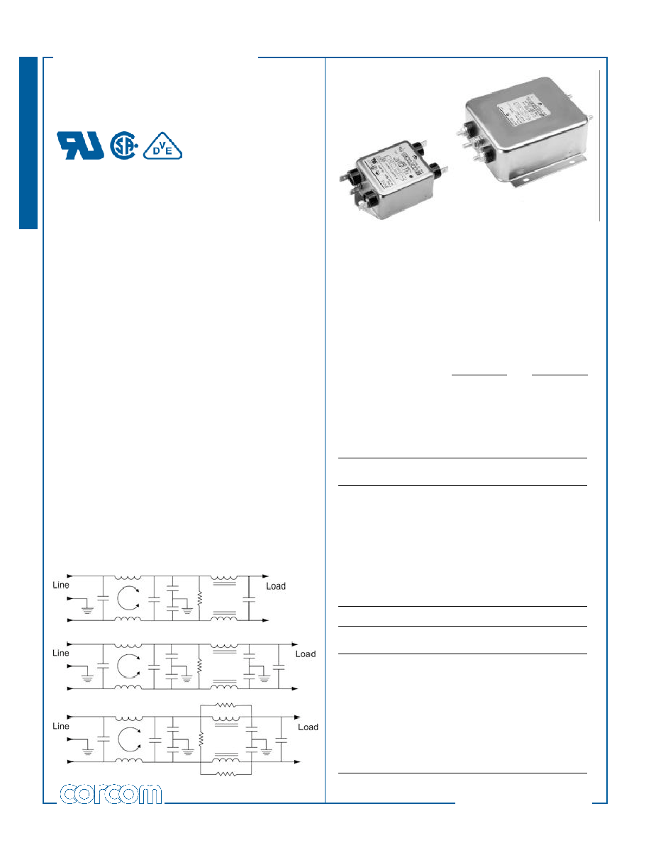
V and W Series
The V series and W series filters will protect equipment
from malfunctions due to conducted interference coming
into the equipment from the line, especially line-to-line
noise and transients. They will also provide needed noise
suppression to allow most equipment to meet FCC
specifications for conducted emissions.
V Series – offers an N = 3 (“T”) line-to-ground
impedance to common mode and an N = 5 (“Dbl. Pi”)
impedance for line-to-line differential mode interference.
The filters are designed for susceptibility use when
equipment impedance at RF frequencies is low.
W Series – provides an N = 4 (“Dbl. L”) line-to-ground
impedance for common mode and an N = 5 (“Dbl. Pi”)
impedance for line-to-line differential mode interference.
The filters are designed for use when equipment
impedance at RF frequencies is high. The two-stage
construction provides excellent suppression at high
frequency.
V series and W series filters are also effective to control
emissions in equipment using SCR and T2L circuits, for
compliance with FCC Part 15, Subpart J, and EN55022,
Level A, down to 150kHz.
Electrical Schematics
V Series
相關(guān)PDF資料 |
PDF描述 |
|---|---|
| 6VV1 | 120 V, 50/60 HZ, SINGLE PHASE EMI FILTER |
| 6VW1 | 120 V, 50/60 HZ, SINGLE PHASE EMI FILTER |
| 7-OR-RT-SA/549 | FIBER OPTIC TRANSMITTER, SC/APC CONNECTOR |
| 7-OR-RT-SA/559 | FIBER OPTIC TRANSMITTER, SC/APC CONNECTOR |
| 7-OR-RT-SA/304 | FIBER OPTIC TRANSMITTER, SC/APC CONNECTOR |
相關(guān)代理商/技術(shù)參數(shù) |
參數(shù)描述 |
|---|---|
| 6VX 5.0AH | 制造商:Murata Power Solutions 功能描述:STATIONARY BATTERY VALVE-REGULATED 5 A |
| 6W-0619-02 | 制造商:INDUSTRIAL WIRE 功能描述:6-1C MTW 600V STR (19 STR) 4/64 INSULATION /BLACK JKT |
| 6W-0819-02 | 制造商:ATLAS 功能描述:8-1/C 600V 19STR PVC MTW 90C UL 1028 105C |
| 6W-0819-03 | 制造商:KALAS 功能描述:MTW-8AWG-RED STRAND |
| 6W-1 | 制造商:Aavid Thermalloy 功能描述:HEAT SINK 1.1/W 制造商:Aavid Thermalloy 功能描述:HEAT SINK, 1.1C/W |
發(fā)布緊急采購,3分鐘左右您將得到回復(fù)。