- 您現(xiàn)在的位置:買賣IC網(wǎng) > PDF目錄97780 > 5962-8687701PA COMPARATOR, 4000 uV OFFSET-MAX, 200 ns RESPONSE TIME, CQCC20 PDF資料下載
參數(shù)資料
| 型號: | 5962-8687701PA |
| 元件分類: | 比較器 |
| 英文描述: | COMPARATOR, 4000 uV OFFSET-MAX, 200 ns RESPONSE TIME, CQCC20 |
| 封裝: | CERAMIC, LCC-20 |
| 文件頁數(shù): | 20/21頁 |
| 文件大?。?/td> | 1678K |
| 代理商: | 5962-8687701PA |
Voltage
Comparator
AS111
Micross Components reserves the right to change products or specications without notice.
8
AS111
Rev. 1.7 01/10
(continued)
APPLICATION HINTS (CONTINUED)
4. When comparator circuits use input resistors (eg.
sum-
ming resistors), their value and placement are
par-
ticularly important. In all cases the body of the resistor
should be close to the device or socket. In other words
there should be very little lead length or printed-circuit
foil run between comparator and resistor to radiate or pick
up signals. The same applies to capacitors, pots, etc. For
example, if R
S=10 kW, as little as 5 inches of lead between
the resistors and the input pins can result placing resistors
close to the comparator.
5. Since feedback to almost any pin of a comparator can
result in oscillation, the printed-circuit layout should be
engineered thoughtfully. Preferably there should be a
groundplane under the AS111 circuitry, for example, one
side of a double-layer circuit card. Ground foil (or, positive
supply or negative supply foil) should extend between the
output and the inputs, to act as a guard. The foil
con-
nections for the inputs should be as small and compact as
possible, and should be essentially surrounded by ground
foil on all sides, to guard against capacitive
cou-
pling from any high-level signals (such as the output). If
pins 5 and 6 are not used, they should be shorted
to-
gether. If they are connected to a trim-pot, the trim-pot
should be located, at most, a few inches away from the
AS111, and the 0.01 μF capacitor should be installed. If
this capacitor cannot be used, a shielding printed-circuit
foil may be advisable between pins 6 and 7. The power
supply bypass capacitors should be located within a couple
inches of the AS111. (Some other comparators require the
power-supply bypass to be located immediately adjacent
to the comparator.)
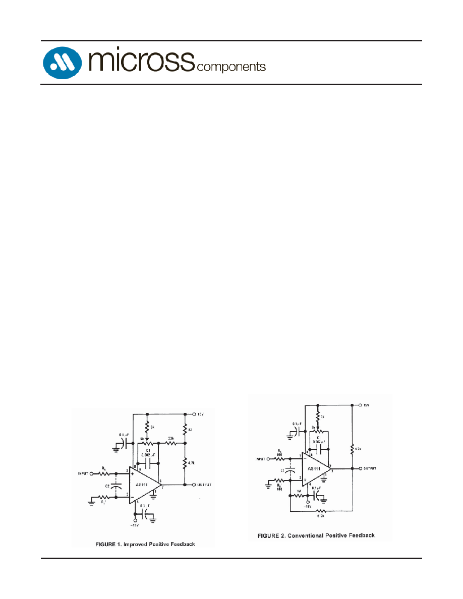
6. It is a standard procedure to use hysteresis (positive
feedback) around a comparator, to prevent oscillation, and
to avoid excessive noise on the output because the
com-
parator is a good amplier for its own noise. In the circuit
of Figure 2, the feedback from the output to the positive
input will cause about 3 mV of hysteresis.
However,
if R
S is larger than 100Ω, such as 50 kΩ, it would not be
reasonable to simply increase the value of the
positive
feedback resistor above 510 k
Ω. The circuit of Figure 3
could be used, but it is rather awkward. See the notes in
paragraph 7 below.
7. When both inputs of the AS111 are connected to ac-
tive signals, or if a high-impedance signal is driving the
positive input of the AS111 so that positive feedback
would be disruptive, the circuit of Figure 1 is ideal. The
positive feedback is to pin 5 (one of the offset adjustment
pins). It is sufcient to cause 1 to 2 mV hysteresis and
sharp
transitions with input triangle waves from a
few Hz to hundreds of kHz. The positive-feedback signal
across the 82
Ω resistor swings 240 mV below the positive
supply. This signal is centered around the nominal voltage
at pin 5, so this feedback does not add to the V
OS of the
comparator. As much as 8 mV of V
OS can be trimmed out,
using the 5 k
Ω pot and 3 kΩ resistor as shown.
8. These application notes apply specically to the AS111
family of comparators, and are applicable to all high-speed
comparators in general, (with the exception that not all
comparators have trim pins).
NOTE: Pin connections shown are for the TO08 can package.
相關(guān)PDF資料 |
PDF描述 |
|---|---|
| 5926-86877012A | COMPARATOR, 4000 uV OFFSET-MAX, 200 ns RESPONSE TIME, CQCC20 |
| 5962-8687701GX | COMPARATOR, 4000 uV OFFSET-MAX, 200 ns RESPONSE TIME, MBCY8 |
| 5962-8687701PX | COMPARATOR, 4000 uV OFFSET-MAX, 200 ns RESPONSE TIME, CDIP8 |
| 5962-8688701CB | DUAL OP-AMP, 180 uV OFFSET-MAX, 8 MHz BAND WIDTH, CDIP8 |
| 5962-8688701CC | DUAL OP-AMP, 180 uV OFFSET-MAX, 8 MHz BAND WIDTH, CDIP8 |
相關(guān)代理商/技術(shù)參數(shù) |
參數(shù)描述 |
|---|---|
| 59628687701Q2A | 制造商:Texas Instruments 功能描述:Comparator Single ±18V/36V 20-Pin CLLCC Rail |
| 5962-8687701Q2A | 制造商:Rochester Electronics LLC 功能描述: 制造商:Texas Instruments 功能描述: |
| 5962-8687702PA | 制造商:Linear Technology 功能描述:SMD |
| 5962-86879013A | 制造商:Rochester Electronics LLC 功能描述:SMD 28 LCC -55+125C ARINC BUS INTERFACE LINE DRIVER - Bulk |
| 5962-8687901EA | 制造商:Holt Integrated Circuits 功能描述:ARINC 429 Differential Line Driver 16-Pin SBCDIP 制造商:Intersil Corporation 功能描述:LINE DRVR 16PIN SBCDIP - Rail/Tube 制造商:Intersil Corporation 功能描述:Line Driver 16-Pin SBCDIP |
發(fā)布緊急采購,3分鐘左右您將得到回復(fù)。