- 您現(xiàn)在的位置:買賣IC網(wǎng) > PDF目錄116761 > 550HFFREQBGR (SILICON LABORATORIES) VCXO, CLOCK, 10 MHz - 945 MHz, CMOS OUTPUT PDF資料下載
參數(shù)資料
| 型號: | 550HFFREQBGR |
| 廠商: | SILICON LABORATORIES |
| 元件分類: | VCXO, clock |
| 英文描述: | VCXO, CLOCK, 10 MHz - 945 MHz, CMOS OUTPUT |
| 封裝: | ROHS COMPLIANT PACKAGE-6 |
| 文件頁數(shù): | 44/45頁 |
| 文件大小: | 691K |
| 代理商: | 550HFFREQBGR |
第1頁第2頁第3頁第4頁第5頁第6頁第7頁第8頁第9頁第10頁第11頁第12頁第13頁第14頁第15頁第16頁第17頁第18頁第19頁第20頁第21頁第22頁第23頁第24頁第25頁第26頁第27頁第28頁第29頁第30頁第31頁第32頁第33頁第34頁第35頁第36頁第37頁第38頁第39頁第40頁第41頁第42頁第43頁當前第44頁第45頁
Si550
8
Rev. 0.5
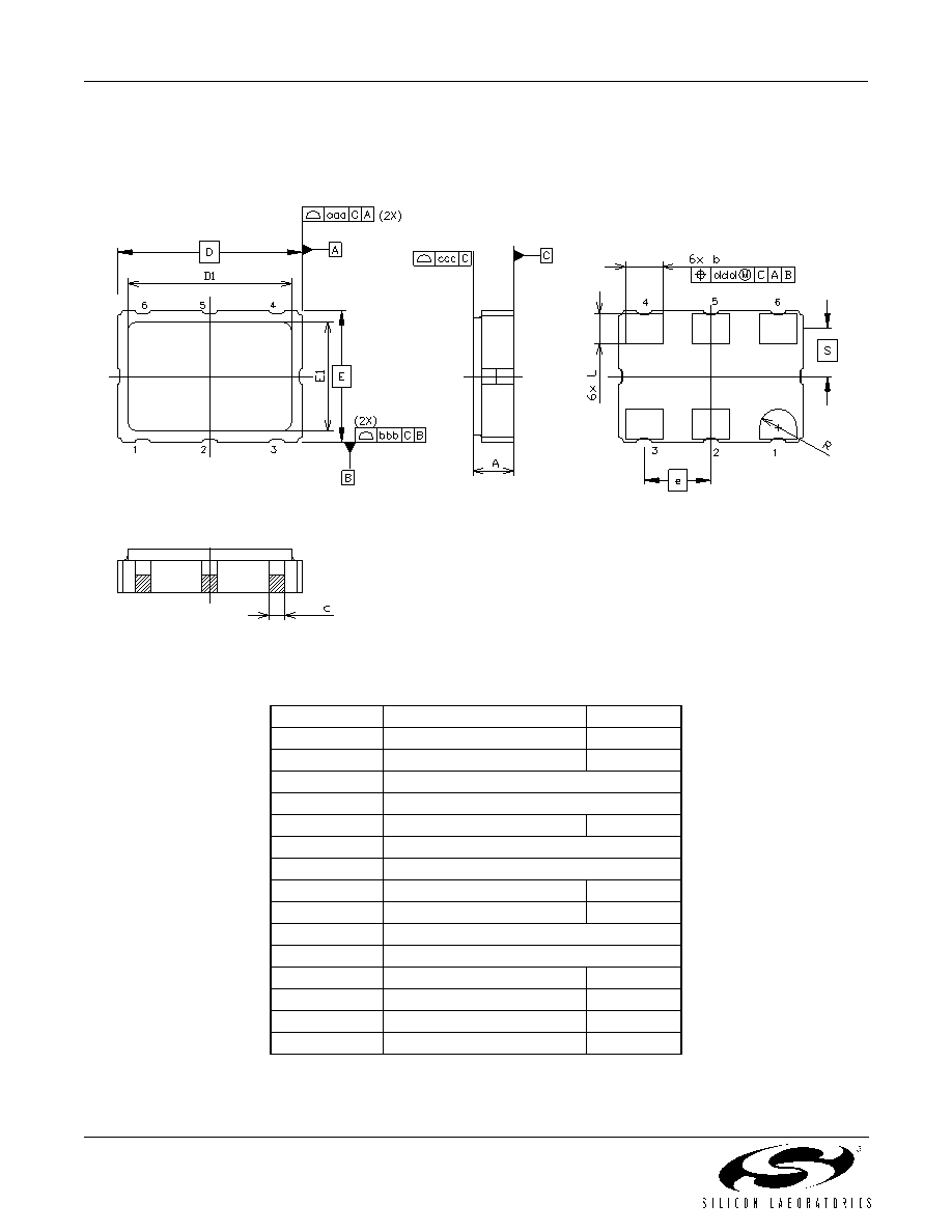
4. Outline Diagram and Suggested Pad Layout
Figure 2 illustrates the package details for the Si550. Table 11 lists the values for the dimensions shown in the
illustration.
Figure 2. Si550 Outline Diagram
Table 11. Package Diagram Dimensions (mm)
Dimension
Min
Nom
Max
A
1.45
1.65
1.85
b1.2
1.4
1.6
c0.60 TYP.
D
7.00 BSC.
D1
6.10
6.2
6.30
e
2.54 BSC.
E
5.00 BSC.
E1
4.30
4.40
4.50
L
1.07
1.27
1.47
S
1.815 BSC.
R
0.7 REF.
aaa
—
0.15
bbb
—
0.15
ccc
—
0.10
ddd
—
0.10
相關PDF資料 |
PDF描述 |
|---|---|
| 550JAFREQBG | VCXO, CLOCK, 10 MHz - 160 MHz, CMOS OUTPUT |
| 550KDFREQBG | VCXO, CLOCK, 10 MHz - 945 MHz, CMOS OUTPUT |
| 550NAFREQBG | VCXO, CLOCK, 10 MHz - 945 MHz, LVDS OUTPUT |
| 550PDFREQBG | VCXO, CLOCK, 10 MHz - 160 MHz, CMOS OUTPUT |
| 550PFFREQBGR | VCXO, CLOCK, 10 MHz - 160 MHz, CMOS OUTPUT |
相關代理商/技術參數(shù) |
參數(shù)描述 |
|---|---|
| 550HG500M000DG | 制造商:Silicon Laboratories Inc 功能描述:CNTRLD OSC 500MHZ VCXO CML 6SMD - Trays |
| 550HG500M000DGR | 制造商:Silicon Laboratories Inc 功能描述:CNTRLD OSC 500MHZ VCXO CML 6SMD - Tape and Reel |
| 550HJ644M531DG | 功能描述:VCXO振蕩器 SNGL XCVO 6PIN 7mm x 5mm RoHS:否 制造商:Fox 封裝 / 箱體:5 mm x 3.2 mm 頻率:19.2 Mhz 頻率穩(wěn)定性:2.5 PPM 輸出格式: 封裝:Reel 電源電壓:3 V 端接類型:SMD/SMT 尺寸:3.2 mm W x 5 mm L x 1.5 mm H 最小工作溫度:- 20 C 最大工作溫度:+ 75 C |
| 550JD100M000DG | 功能描述:VCXO振蕩器 SNGL VCXO 6 PIN 7mm x 5mm RoHS:否 制造商:Fox 封裝 / 箱體:5 mm x 3.2 mm 頻率:19.2 Mhz 頻率穩(wěn)定性:2.5 PPM 輸出格式: 封裝:Reel 電源電壓:3 V 端接類型:SMD/SMT 尺寸:3.2 mm W x 5 mm L x 1.5 mm H 最小工作溫度:- 20 C 最大工作溫度:+ 75 C |
| 550KC148M352DG | 制造商:Silicon Laboratories Inc 功能描述:OSCILLATOR - Trays |
發(fā)布緊急采購,3分鐘左右您將得到回復。