- 您現(xiàn)在的位置:買賣IC網(wǎng) > PDF目錄360230 > 522925X IC PDF資料下載
參數(shù)資料
| 型號(hào): | 522925X |
| 英文描述: | IC |
| 中文描述: | 集成電路 |
| 文件頁(yè)數(shù): | 9/24頁(yè) |
| 文件大?。?/td> | 418K |
| 代理商: | 522925X |
第1頁(yè)第2頁(yè)第3頁(yè)第4頁(yè)第5頁(yè)第6頁(yè)第7頁(yè)第8頁(yè)當(dāng)前第9頁(yè)第10頁(yè)第11頁(yè)第12頁(yè)第13頁(yè)第14頁(yè)第15頁(yè)第16頁(yè)第17頁(yè)第18頁(yè)第19頁(yè)第20頁(yè)第21頁(yè)第22頁(yè)第23頁(yè)第24頁(yè)
9
LTC1286/LTC1298
1
2
3
4
LTC1298
D
IN
CLK
D
OUT
START
t
en
B11
V
OL
LTC1286/98 TC07
CS
TEST CIR
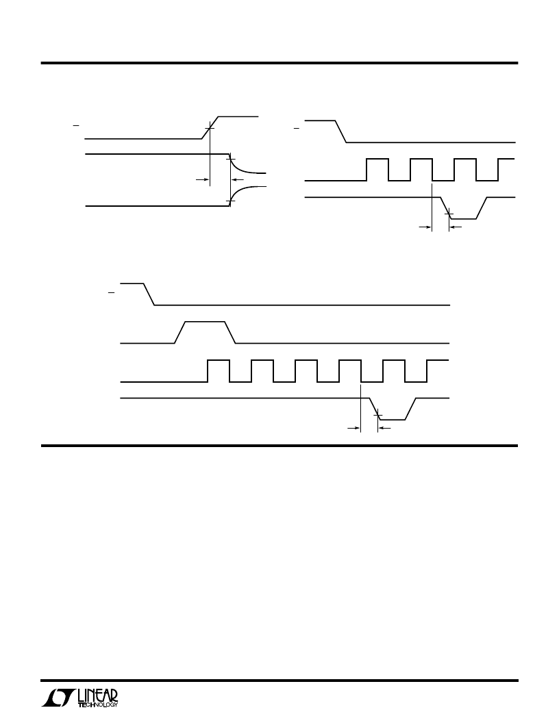
Voltage Waveforms for t
dis
Voltage Waveforms for t
en
Voltage Waveforms for t
en
D
WAVEFORM 1
(SEE NOTE 1)
V
IH
t
dis
90%
10%
D
OUT
WAVEFORM 2
(SEE NOTE 2)
NOTE 1: WAVEFORM 1 IS FOR AN OUTPUT WITH INTERNAL CONDITIONS SUCH
THAT THE OUTPUT IS HIGH UNLESS DISABLED BY THE OUTPUT CONTROL.
NOTE 2: WAVEFORM 2 IS FOR AN OUTPUT WITH INTERNAL CONDITIONS SUCH
THAT THE OUTPUT IS LOW UNLESS DISABLED BY THE OUTPUT CONTROL.
CS
LTC1286/98 TC05
LTC1286/98 TC06
CS
LTC1286
1
CLK
D
OUT
t
en
B11
V
OL
2
APPLICATIO
I
FOR
ATIO
U
OVERVIEW
The LTC1286 and LTC1298 are micropower, 12-bit, suc-
cessive approximation sampling A/D converters. The
LTC1286 typically draws 250
μ
A of supply current when
sampling at 12.5kHz while the LTC1298 nominally con-
sumes 350
μ
A of supply current when sampling at
11.1 kHz. The extra 100
μ
A of supply current on the
LTC1298 comes from the reference input which is inten-
tionally tied to the supply. Supply current drops linearly as
the sample rate is reduced (see Supply Current vs Sample
Rate). The ADCs automatically power down when not
performing conversions, drawing only leakage current.
They are packaged in 8-pin SO and DIP packages. The
LTC1286 operates on a single supply from 4.5V to 9V,
W
U
U
while the LTC1298 operates from a 4.5V to 5.5V supply.
Both the LTC1286 and the LTC1298 contain a 12-bit,
switched-capacitor ADC, a sample-and-hold, and a
serial port (see Block Diagram). Although they share
the same basic design, the LTC1286 and LTC1298
differ in some respects. The LTC1286 has a differential
input and has an external reference input pin. It can
measure signals floating on a DC common-mode volt-
age and can operate with reduced spans to 1V. Reduc-
ing the spans allows it to achieve 244
μ
V resolution. The
LTC1298 has a two-channel input multiplexer and can
convert either channel with respect to ground or the
difference between the two. The reference input is tied
to the supply pin.
相關(guān)PDF資料 |
PDF描述 |
|---|---|
| 52602499 | LOETSTATION WECP 82 |
| 52610-1090 | Dual/Triple Ultra-Low-Voltage SOT23 µP Supervisory Circuits |
| 52610-2090 | STECKVERBINDER 1.0MM SMT VERT 20POL |
| 52610-2690 | Dual/Triple Ultra-Low-Voltage SOT23 µP Supervisory Circuits |
| 52610-3090 | STECKVERBINDER 1.0MM SMT VERT 30POL |
相關(guān)代理商/技術(shù)參數(shù) |
參數(shù)描述 |
|---|---|
| 522928E | 制造商:未知廠家 制造商全稱:未知廠家 功能描述:IC |
| 522929C | 制造商:未知廠家 制造商全稱:未知廠家 功能描述:IC |
| 5229-2SF | 制造商:Carlisle Interconnect Components 功能描述:RF COAXIAL PANEL MOUNT CONNECTOR |
| 522-93-012-05-001001 | 制造商:Mill-Max Mfg Corp 功能描述:Conn PGA Socket SKT 12 POS Solder ST Thru-Hole |
| 522-93-012-05-001002 | 功能描述:SKT PGA WRAPOST 制造商:mill-max manufacturing corp. 系列:* 零件狀態(tài):在售 標(biāo)準(zhǔn)包裝:50 |
發(fā)布緊急采購(gòu),3分鐘左右您將得到回復(fù)。