- 您現(xiàn)在的位置:買賣IC網(wǎng) > PDF目錄114411 > 40IMX7-05-9Z (POWER-ONE INC) 1-OUTPUT 6.1 W DC-DC REG PWR SUPPLY MODULE PDF資料下載
參數(shù)資料
| 型號: | 40IMX7-05-9Z |
| 廠商: | POWER-ONE INC |
| 元件分類: | 電源模塊 |
| 英文描述: | 1-OUTPUT 6.1 W DC-DC REG PWR SUPPLY MODULE |
| 文件頁數(shù): | 2/15頁 |
| 文件大小: | 213K |
| 代理商: | 40IMX7-05-9Z |
IMX 7 DC/DC Series Data Sheet
7W Board Mountable Converter
REV. OCT 01, 2003
10/15
IMX SERIES
R
Vo+
Vo–
+
U
ext
–
4 k
Uref 2.5 V
control
circuit
Vi+
Vi–
R
ext1
R
ext 2
06029
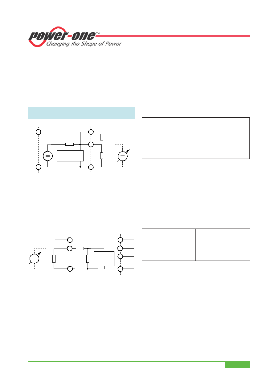
Fig. 13
Output voltage control for single output units by means of
the R-input
Double output units:
The R input (Trim) input is referenced to the primary side.
The figure below shows the circuit topology. Adjustment of
the output voltage is possible by means of either an exter-
nal resistor in the range of 100...105% of Vo nom, or an ex-
ternal voltage source in the range of 75...105% of Vo nom.
R (Trim)
Vo1+
Vo2–
+
U
ext
–
Vi+
Vi–
R
ext
Vo1–
Vo2+
06030
Control
circuit
Uref 2.5 V
Fig. 14
Output voltage control for double output units by means
of the R input
a) Adjustment by means of an external resistor.
Programming of the output voltage by means of an ex-
ternal resistor Rext1 is possible within a limited range of
100...105% of Vo nom. Rext1 should be connected be-
tween the R-pin and Vi–. Connection of Rext1 to Vi+ may
damage the converter. The following table indicates suit-
able resistor values for typical output voltages under
nominal conditions (Vi nom, Io = 0.5 Io nom), with either par-
alleled outputs or equal load conditions on each output.
b) Adjustment by means of an external voltage source Vext.
For external output voltage programming in the range
75...105% of Vo nom a (0...20 V) source Vext is required,
connected to the R-pin and Vi–. The table below indi-
cates typical Vo versus Vext values under nominal condi-
tions (Vi nom, Io = 0.5 Io nom), with either paralleled outputs
or equal load conditions on each output. Applying a con-
trol voltage greater than 20 V will set the converter into a
hiccup mode. Direct paralleling of the R-pins of units
connected in parallel is feasible.
Table 7: Vext for Uo = 75...105% Vo nom;
typical values (Vi nom, Io1, 2 = 0.5 Io1/2 nom)
Vo [% Uo nom]
Vext [V]
105
0
102
1.6
95
4.5
85
9
75
13
b) Adjustment by means of an external voltage Vext be-
tween Vo– and R pins.
The control voltage range is 1.87...2.62 V and allows for
an adjustment in the range of approximately 75...105%.
(85...105% for 3.3 V outputs)
Vo 2.5 V
Vext = –––––––––
Vo nom
Attempting to adjust the output below this range will
cause the converter to shutdown (hiccup mode).
Note: Applying an external control voltage >2.75 V may
damage the converter.
Table 6: Rext1 for Vo > Vo nom;
approximate values (Vi nom, Io1, 2 = 0.5 Io1/2 nom)
Vo [% Vo nom]
Rext [k]
105...108 (107 typically)
0
105
1.5
104
5.6
103
12
102
27
101
68
100
∞
相關(guān)PDF資料 |
PDF描述 |
|---|---|
| 40IMX7-24-24-7XM | 2-OUTPUT 7 W DC-DC REG PWR SUPPLY MODULE |
| 48H1501-2RD6 | 1-OUTPUT DC-DC REG PWR SUPPLY MODULE |
| 40IMX4-2424-7 | 2-OUTPUT 3 W DC-DC REG PWR SUPPLY MODULE |
| 48ICR1-12-12-NS | 2-OUTPUT 1 W DC-DC REG PWR SUPPLY MODULE |
| 48H1901-2RD6 | 1-OUTPUT DC-DC REG PWR SUPPLY MODULE |
相關(guān)代理商/技術(shù)參數(shù) |
參數(shù)描述 |
|---|---|
| 40IMX7-12-12-8 | 功能描述:DC/DC轉(zhuǎn)換器 7W (2x 12V) DC Input (16.8-75V) RoHS:否 制造商:Murata 產(chǎn)品: 輸出功率: 輸入電壓范圍:3.6 V to 5.5 V 輸入電壓(標(biāo)稱): 輸出端數(shù)量:1 輸出電壓(通道 1):3.3 V 輸出電流(通道 1):600 mA 輸出電壓(通道 2): 輸出電流(通道 2): 安裝風(fēng)格:SMD/SMT 封裝 / 箱體尺寸: |
| 40IMX712128G | 制造商:Power-One 功能描述: |
| 40IMX7-12-12-8G | 功能描述:DC/DC轉(zhuǎn)換器 RoHS:否 制造商:Murata 產(chǎn)品: 輸出功率: 輸入電壓范圍:3.6 V to 5.5 V 輸入電壓(標(biāo)稱): 輸出端數(shù)量:1 輸出電壓(通道 1):3.3 V 輸出電流(通道 1):600 mA 輸出電壓(通道 2): 輸出電流(通道 2): 安裝風(fēng)格:SMD/SMT 封裝 / 箱體尺寸: |
| 40IMX712128ZG | 制造商:Power-One 功能描述: |
| 40IMX7-12-12-9 | 制造商:POWER-ONE 制造商全稱:Power-One 功能描述:7 Watt DC-DC Converters |
發(fā)布緊急采購,3分鐘左右您將得到回復(fù)。