- 您現(xiàn)在的位置:買賣IC網(wǎng) > PDF目錄226111 > 40IMX15-15-15-8K-G (POWER-ONE INC) 2-OUTPUT 16.8 W DC-DC REG PWR SUPPLY MODULE PDF資料下載
參數(shù)資料
| 型號: | 40IMX15-15-15-8K-G |
| 廠商: | POWER-ONE INC |
| 元件分類: | 電源模塊 |
| 英文描述: | 2-OUTPUT 16.8 W DC-DC REG PWR SUPPLY MODULE |
| 封裝: | 2 INCH X 1.600 INCH, 10.50 MM HEIGHT, PACKAGE-7 |
| 文件頁數(shù): | 13/20頁 |
| 文件大?。?/td> | 186K |
| 代理商: | 40IMX15-15-15-8K-G |
Board Mountable
DC-DC Converters
IMX/IMY 15 Series
Edition 5/06.2001
20/20
Option -8
Extended Temperature Range
Extension of the temperature range from standard
–40...85
°C. In the upper temperature range the output
power derating below should be observed. The modules
will provide the specified output power with free air convec-
tion cooling.
Option K
Alternative Pinout
Option K configures the electrically isolated double outputs
to the alternative pinout with outputs connected in series
(Vo+/Go/Vo–) and common ground.
However instead of using units with option K, it is recom-
mended to use the standard double output units by provid-
ing the printed circuit board with an additional pin hole (for
pin 12 of double output units) connected to pin hole 13. This
will provide more design-in flexibility since by that both
pinouts may be used on the same PCB.
Option i
Inhibit
Excludes shut down and option K.
The output(s) of the converter may be enabled or disabled
by means of a logic signal (TTL, CMOS, etc.) applied to the
inhibit pin. No output voltage overshoot will occur when the
unit is turned on. If the inhibit function is not required the
inhibit pin should be connected to Vi– to enable the output
(active low logic, fail safe).
Converter operating:
–10 V...0.8 V
Converter inhibited
or inhibit left open circuit:
2.4 V...
Ui max (<75 V)
Fig. 31
If the inhibit is not used the inhibit pin should be con-
nected to Vi–
Vi+
Vi –
i
06070
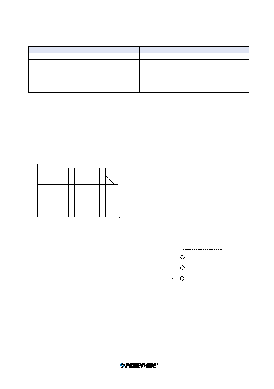
1.2
1.0
0.8
0.6
0.4
0
20
–20
60
0.2
40
80
Po/Po max
TA [°C]
–40
0
11047
Fig. 30
Maximum allowed output power versus ambient tempera-
ture.
Description of Options
Table 18: Survey of options
Option
Function of option
Characteristic
–8
Extended operational ambient temperature range
TA = –40...85°C
K
Alternativ pinout
See mechanical data
i
Inhibit
C
C-pinout
See mechanical data
L
Surface mount version with PCB lid
See mechanical data
Z
Open frame
See mechanical data
相關(guān)PDF資料 |
PDF描述 |
|---|---|
| 48H1601-7RV3 | 1-OUTPUT DC-DC REG PWR SUPPLY MODULE |
| 48S3.4000NT | 1-OUTPUT 20 W DC-DC REG PWR SUPPLY MODULE |
| 48S12.4HEN | 1-OUTPUT DC-DC REG PWR SUPPLY MODULE |
| 48S12.4HE | 1-OUTPUT 50 W DC-DC REG PWR SUPPLY MODULE |
| 40IMR3-12-2 | 1-OUTPUT 3 W DC-DC REG PWR SUPPLY MODULE |
相關(guān)代理商/技術(shù)參數(shù) |
參數(shù)描述 |
|---|---|
| 40IMX-15-15-15-8R | 制造商:Power-One 功能描述:POWER SUPPLIES MISC.MELCHER PART - Bulk |
| 40IMX15-15-15-8R | 制造商:Power-One 功能描述:POWER SUPPLIES MISC.MELCHER PART - Bulk |
| 40IMX15-15-15-9 | 制造商:Power-One 功能描述: |
| 40IMX15-15-9C | 制造商:POWER-ONE 制造商全稱:Power-One 功能描述:15 Watt DC-DC Converters |
| 40IMX15-2.5-9RG | 制造商:POWER-ONE 制造商全稱:Power-One 功能描述:15 Watt DC-DC Converters |
發(fā)布緊急采購,3分鐘左右您將得到回復。