- 您現(xiàn)在的位置:買賣IC網(wǎng) > PDF目錄155700 > 24IMS15-15-15-9L 2-OUTPUT 16.8 W DC-DC REG PWR SUPPLY MODULE PDF資料下載
參數(shù)資料
| 型號: | 24IMS15-15-15-9L |
| 元件分類: | 電源模塊 |
| 英文描述: | 2-OUTPUT 16.8 W DC-DC REG PWR SUPPLY MODULE |
| 文件頁數(shù): | 10/14頁 |
| 文件大小: | 265K |
| 代理商: | 24IMS15-15-15-9L |
Board Mountable
DC-DC Converters
IMS 15 Series
Edition 6/5.2000
5/14
Input Transient Voltage Protection
A built-in suppressor diode provides effective protection
against input transients which may be caused for example
by short-circuits accross the input lines where the network
inductance may cause high energy pulses.
Table 3: Built-in transient voltage suppressor
Type
Breakdown
Peak power
Peak pulse
voltage
at 1 ms
current
VBR nom [V]
PP [W]
IPP [A]
24 IMS 15
53
600
7.7
48 IMS 15
100
600
4.1
For very high energy transients as for example to achieve
IEC/EN 61000-4-5 or ETR 283 (19 Pfl1) compliance (as per
table
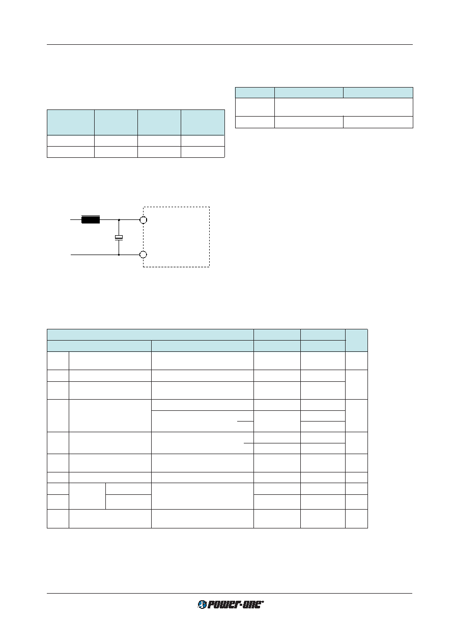
:Electromagnetic Immunity) an external inductor and
capacitor are required.
Vi+
Vi–
C
L
V+
V–
Module
+
04009
1
2
Fig. 7
Example for external circuitry to comply with
IEC/EN 61000-4-5 or ETR 283 (19 Pfl1) (48 IMS15 types).
Table 4: Components for external circuitry to comply with
IEC/EN 61000-4-5, level 2 or ETR 283 (19Pfl1)
(48 IMS types).
Circuit Ref.
24 IMS 15
48 IMS 15
L
150
H, 0.294 , 640 mA
TOKO: 494 LYF-0094K 1
C
150
F, 63 V, 85°C
100
F, 150 V, 85°C
1 Available from TOKO Components Division
Reverse Polarity Protection at the Input
The built-in suppressor diode also provides for reverse po-
larity protection at the input by conducting current in the re-
verse direction. An external fuse is required to limit this cur-
rent.
– For 24 IMS 15 types a fast 3.15 A (F3.15A) fuse is
recommended.
– For 48 IMS 15 types a fast 2 A (F2A) fuse is recom-
mended.
Electrical Output Data
General conditions:
TA = 25
°C, unless T
C is specified. Shut down pin left open (not connected). Trim- or R-input not connected.
Table 5a: Output data for single output units and -0503- types.
Output
5.1 V
5.1/3.3 V
Characteristics
Conditions
min typ max
Unit
Uo1
Output voltage
Ui nom
5.05
5.15
5.0
5.12
V
Uo2
Io = 0.5 Io nom
3.13
3.46
Io nom
Output current 1
Ui min...Ui max
2.7
2
× 1.6
A
Io1L
Current limit 2, 4
Ui nom, TC = 25°C
3.5
3.0
Io2L
Uo = 90% Uo nom
3.8
DUo
Line/load regulation
Ui min...Ui max, Io = (0.01...1) Io nom
±0.5
%
Ui min...Ui max
5.1 V
+3, –5
Io = (0.1...1) Io nom
3.3 V
±4.5
uo1/2
Output voltage noise
Ui min...Ui max
5
70
80
mVpp
Io = Io nom
6
40
Uo L
Output overvoltage
115
130
115
130
%
limitation
Co ext
Admissible capacitive load 3
4000
total 4000
F
uo d
Dynamic
Voltage deviat.
Ui nom
±250
±150
mV
td
load
Recovery time
Io nom 1/2 Io nom
11
ms
regulation
IEC/EN 61204
aUo
Temperature coefficient
Ui min...Ui max
±0.02
±0.02 %/K
DUo/DTC
Io = 0...Io max
1 Flexible load distribution: 24/48 IMS 15-0503 types; 2 A max. on one of the 2 outputs, the other output should not be loaded such that
the total output power exceeds
Po nom according to table: Type survey.
2 The current limit is primary side controlled.
3 Measured with both outputs connected in parallel. For -0503- types: total capacitance, both outputs.
4 Conditions for specified output. Other output loaded with constant current Io = 0.5 Io nom.
5 BW = 20 MHz
6 Measured with a probe according to EN 61204
7 The overvoltage protection is not tracking with R/Trim control.
相關(guān)PDF資料 |
PDF描述 |
|---|---|
| 24IMS15-24-24-9I | 2-OUTPUT 16.8 W DC-DC REG PWR SUPPLY MODULE |
| 48IMS15-05-05-9Z | 2-OUTPUT 14 W DC-DC REG PWR SUPPLY MODULE |
| 48IMS15-12-12-9I | 2-OUTPUT 16.8 W DC-DC REG PWR SUPPLY MODULE |
| 24IMS25-03-9GI | 1-OUTPUT 19.8 W DC-DC REG PWR SUPPLY MODULE |
| 24IMS25-03-9GIZ | 1-OUTPUT 19.8 W DC-DC REG PWR SUPPLY MODULE |
相關(guān)代理商/技術(shù)參數(shù) |
參數(shù)描述 |
|---|---|
| 24IMS15-15-9C | 制造商:POWER-ONE 制造商全稱:Power-One 功能描述:15 Watt DC-DC Converters |
| 24IMS15-24-24-9 | 功能描述:DC/DC轉(zhuǎn)換器 15W (2x 24V) DC Input (14-36V) RoHS:否 制造商:Murata 產(chǎn)品: 輸出功率: 輸入電壓范圍:3.6 V to 5.5 V 輸入電壓(標(biāo)稱): 輸出端數(shù)量:1 輸出電壓(通道 1):3.3 V 輸出電流(通道 1):600 mA 輸出電壓(通道 2): 輸出電流(通道 2): 安裝風(fēng)格:SMD/SMT 封裝 / 箱體尺寸: |
| 24IMS15-24-24-9G | 制造商:Power-One 功能描述:CONV DC-DC DUAL-OUT 24V-IN 9PIN - Bulk |
| 24IMS15-24-24-9-G | 功能描述:DC/DC轉(zhuǎn)換器 RoHS:否 制造商:Murata 產(chǎn)品: 輸出功率: 輸入電壓范圍:3.6 V to 5.5 V 輸入電壓(標(biāo)稱): 輸出端數(shù)量:1 輸出電壓(通道 1):3.3 V 輸出電流(通道 1):600 mA 輸出電壓(通道 2): 輸出電流(通道 2): 安裝風(fēng)格:SMD/SMT 封裝 / 箱體尺寸: |
| 24IMS25-03-9G | 制造商:Power-One 功能描述: |
發(fā)布緊急采購,3分鐘左右您將得到回復(fù)。