- 您現(xiàn)在的位置:買賣IC網(wǎng) > PDF目錄155699 > 24C04A (Microchip Technology Inc.) 4K 5.0V I 2 C ⑩ Serial EEPROM PDF資料下載
參數(shù)資料
| 型號(hào): | 24C04A |
| 廠商: | Microchip Technology Inc. |
| 英文描述: | 4K 5.0V I 2 C ⑩ Serial EEPROM |
| 中文描述: | 4K的5.0VI 2葷⑩串行EEPROM |
| 文件頁(yè)數(shù): | 11/12頁(yè) |
| 文件大?。?/td> | 107K |
| 代理商: | 24C04A |
24C04A
DS11183E-page 8
1998 Microchip Technology Inc.
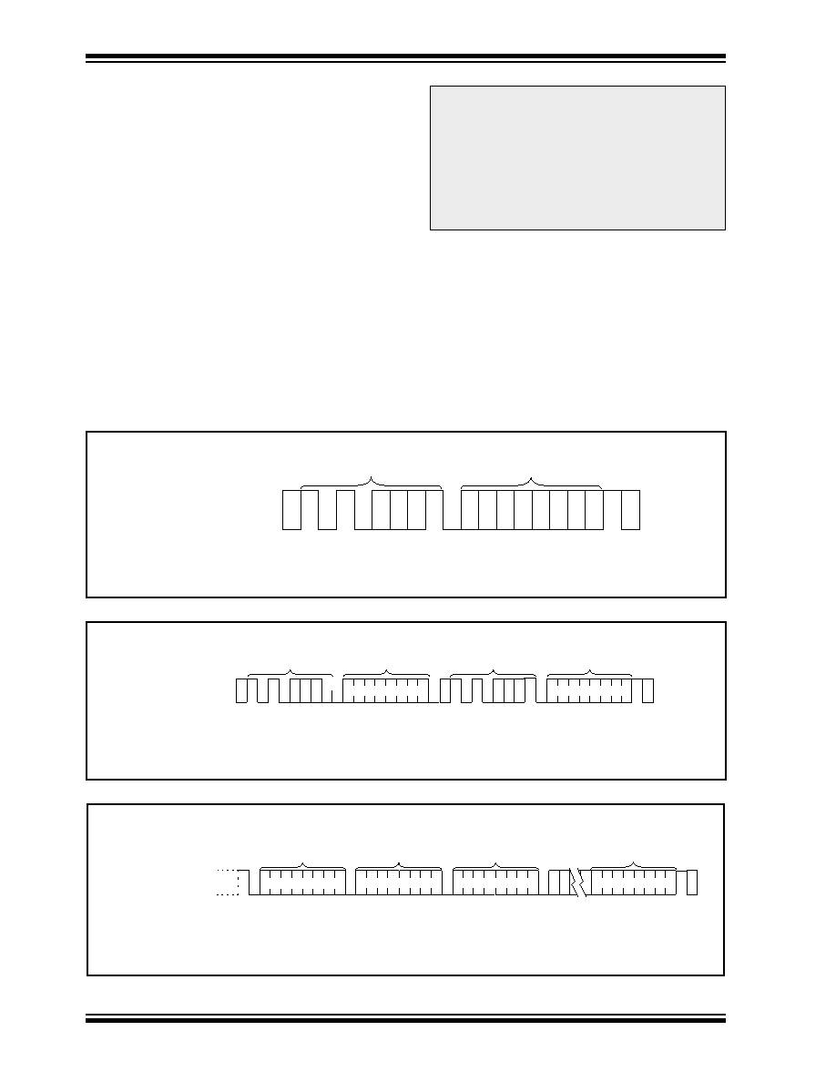
FIGURE 9-1:
CURRENT ADDRESS READ
FIGURE 9-2:
RANDOM READ
FIGURE 9-3:
SEQUENTIAL READ
SP
BUS ACTIVITY
MASTER
SDA LINE
BUS ACTIVITY
S
T
A
R
T
S
T
O
P
CONTROL
BYTE
DATA n
A
C
K
N
O
A
C
K
S
P
S
BUS ACTIVITY
MASTER
SDA LINE
BUS ACTIVITY
S
T
A
R
T
S
T
O
P
CONTROL
BYTE
A
C
K
WORD
ADDRESS (n)
CONTROL
BYTE
S
T
A
R
T
DATA (n)
A
C
K
A
C
K
N
O
A
C
K
P
BUS ACTIVITY
MASTER
SDA LINE
BUS ACTIVITY
S
T
O
P
CONTROL
BYTE
A
C
K
N
O
A
C
K
DATA n
DATA n + 1
DATA n + 2
DATA n + X
A
C
K
A
C
K
A
C
K
9.0
READ MODE
In this mode the 24C04A transmits data to the master
devide.
As can be seen from Figure 9-2 and Figure 9-3, the
master rst sets up the slave and word addresses by
doing a write. (Note: Although this is a read mode, the
address pointer must be written to). During this period
the 24C04A generates the necessary acknowledge
bits as dened in the appropriate section.
The master now generates another START condition
and transmits the slave address again, except this time
the read/write bit is set into the read mode. After the
slave generates the acknowledge bit, it then outputs
the data from the addressed location on to the SDA pin,
increments the address pointer and, if it receives an
acknowledge from the master, will transmit the next
consecutive byte. This auto-increment sequence is
only aborted when the master sends a STOP condition
instead of an acknowledge.
Note 1: If the master knows where the address
pointer is, it can begin the read sequence
at the current address (Figure 9-1) and
save time transmitting the slave and word
addresses.
Note 2: In all modes, the address pointer will not
increment through a block (256 byte)
boundary, but will rotate back to the rst
location in that block.
相關(guān)PDF資料 |
PDF描述 |
|---|---|
| 24C04A-EP | 1K/2K/4K 5.0V I 2 C O Serial EEPROMs |
| 24C04A-ESL | 1K/2K/4K 5.0V I 2 C O Serial EEPROMs |
| 24C04A-ESM | 1K/2K/4K 5.0V I 2 C O Serial EEPROMs |
| 24C04A-ESN | 1K/2K/4K 5.0V I 2 C O Serial EEPROMs |
| 24C04A-IP | 1K/2K/4K 5.0V I 2 C O Serial EEPROMs |
相關(guān)代理商/技術(shù)參數(shù) |
參數(shù)描述 |
|---|---|
| 24C04A/J | 制造商:未知廠家 制造商全稱:未知廠家 功能描述:I2C Serial EEPROM |
| 24C04A-/P | 制造商:未知廠家 制造商全稱:未知廠家 功能描述:I2C Serial EEPROM |
| 24C04A/PA22 | 制造商:Microchip Technology Inc 功能描述: |
| 24C04A-/SL | 制造商:未知廠家 制造商全稱:未知廠家 功能描述:I2C Serial EEPROM |
| 24C04A-/SM | 制造商:未知廠家 制造商全稱:未知廠家 功能描述:I2C Serial EEPROM |
發(fā)布緊急采購(gòu),3分鐘左右您將得到回復(fù)。