- 您現(xiàn)在的位置:買賣IC網(wǎng) > PDF目錄371377 > 230Q1 (Texas Instruments, Inc.) 3.3-V CAN TRANSCEIVERS PDF資料下載
參數(shù)資料
| 型號: | 230Q1 |
| 廠商: | Texas Instruments, Inc. |
| 元件分類: | CAN |
| 英文描述: | 3.3-V CAN TRANSCEIVERS |
| 中文描述: | 3.3 V的CAN收發(fā)器 |
| 文件頁數(shù): | 20/30頁 |
| 文件大小: | 488K |
| 代理商: | 230Q1 |
第1頁第2頁第3頁第4頁第5頁第6頁第7頁第8頁第9頁第10頁第11頁第12頁第13頁第14頁第15頁第16頁第17頁第18頁第19頁當(dāng)前第20頁第21頁第22頁第23頁第24頁第25頁第26頁第27頁第28頁第29頁第30頁
SN65HVD230Q-Q1
SN65HVD231Q-Q1
SN65HVD232Q-Q1
SGLS117C
–
JUNE 2001
–
REVISED JUNE 2002
20
www.ti.com
APPLICATION INFORMATION
features of the SN65HVD230Q, SN65HVD231Q, and SN65HVD232Q (continued)
The bus pins are also maintained in a high-impedance state during low V
CC
conditions to ensure glitch-free
power-up and power-down bus protection for hot-plugging applications. This high-impedance condition also
means that an unpowered node will not disturb the bus. Transceivers without this feature usually have a very
low output impedance. This results in a high current demand when the transceiver is unpowered, a condition
that could affect the entire bus.
operating modes
R
S
(pin 8) of the SN65HVD230Q and SN65HVD231Q provides for three different modes of operation:
high-speed mode, slope-control mode, and low-power standby mode.
high-speed mode
The high-speed mode can be selected by applying a logic low to Rs (pin 8). The high-speed mode of operation
is commonly employed in industrial applications. High-speed allows the output to switch as fast as possible with
no internal limitation on the output rise and fall slopes. The only limitations of the high-speed operation are cable
length and radiated emission concerns, each of which is addressed by the slope control mode of operation.
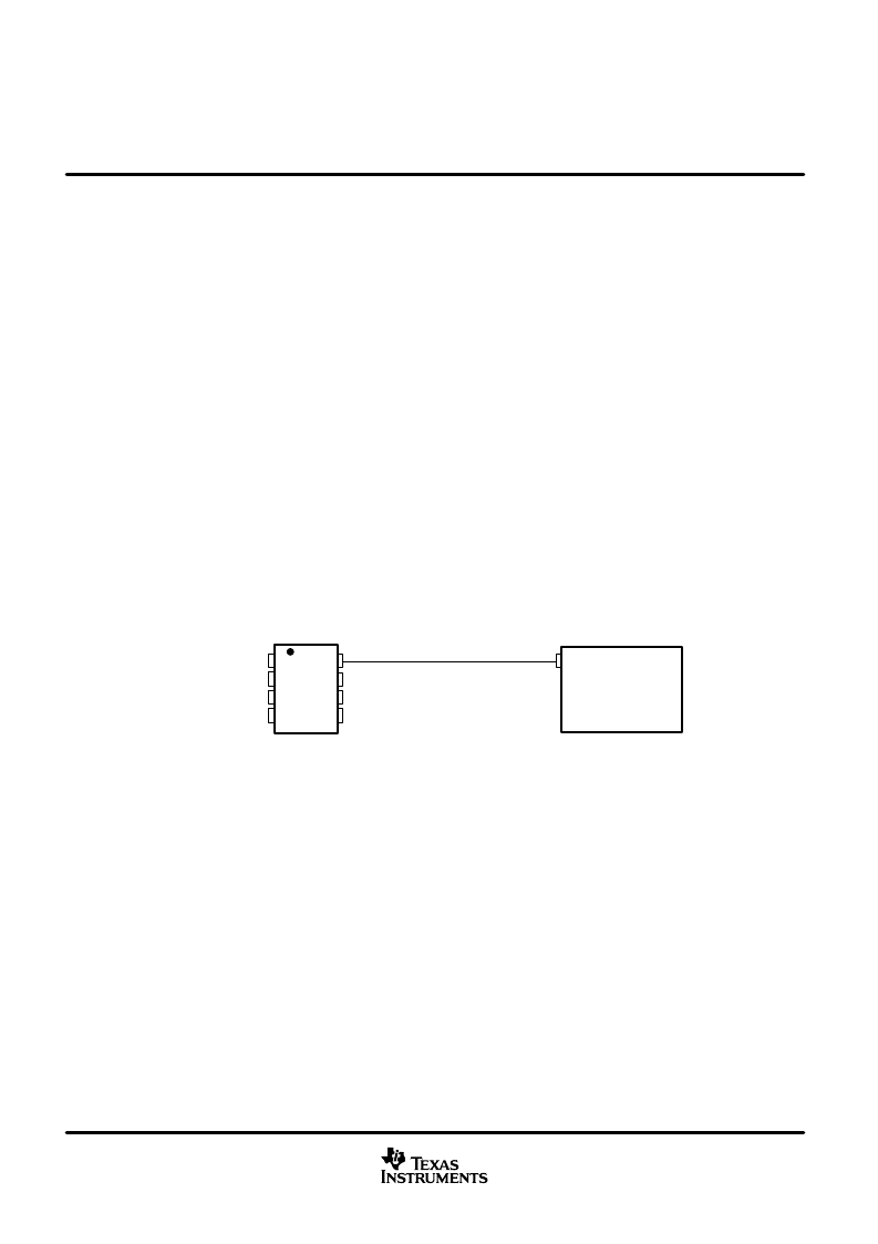
If the low-power standby mode is to be employed in the circuit, direct connection to a DSP output pin can be
used to switch between a logic-low level (< 1 V) for high speed mode operation, and the logic-high level (> 0.75
V
CC
) for standby mode operation. Figure 29 shows a typical DSP connection, and Figure 30 shows the
SN65HVD230Q driver output signal in high-speed mode on the CAN bus.
TMS320LF2406
or
TMS320LF2407
IOPF6
1
2
3
4
8
7
6
5
D
GND
V
CC
R
CANH
CANL
Vref
R
S
SN65HVD230Q
Figure 29. R
S
(Pin 8) Connection to a TMS320LF2406/07 for High-Speed or Standby Mode Operation
相關(guān)PDF資料 |
PDF描述 |
|---|---|
| 231Q1 | 3.3-V CAN TRANSCEIVERS |
| 232Q1 | 3.3-V CAN TRANSCEIVERS |
| 2311086 | SEALANT TEMPFLEX 5140 |
| 23111 | REPOSITIONABLE ADHESIVE 400M |
| 23112 | Using the SmartDMA Controller with USB on the Am186CC Microcontroller Application Note? 156KB (PDF) |
相關(guān)代理商/技術(shù)參數(shù) |
參數(shù)描述 |
|---|---|
| 230SFT117-1 | 制造商: 功能描述: 制造商:undefined 功能描述: |
| 230V CHARGER W/RETRACTABE | 制造商:JO-EL Electric 功能描述:Bulk |
| 230V USB CHARGER | 制造商:JO-EL Electric 功能描述:Bulk |
| 230V-B10A-2 | 制造商:MAXCONN 功能描述:HEADER-3X10-STG |
| 230YXF22MEFC10X16 | 功能描述:CAP ALUM RAD 制造商:rubycon 系列:* 零件狀態(tài):在售 標(biāo)準(zhǔn)包裝:1,000 |
發(fā)布緊急采購,3分鐘左右您將得到回復(fù)。