- 您現(xiàn)在的位置:買賣IC網(wǎng) > PDF目錄370029 > 20H04 (SMSC Corporation) 4-PORT USB2.0 HUB CONTROLLER PDF資料下載
參數(shù)資料
| 型號: | 20H04 |
| 廠商: | SMSC Corporation |
| 英文描述: | 4-PORT USB2.0 HUB CONTROLLER |
| 中文描述: | 4端口USB2.0集線器控制器 |
| 文件頁數(shù): | 12/38頁 |
| 文件大小: | 919K |
| 代理商: | 20H04 |
第1頁第2頁第3頁第4頁第5頁第6頁第7頁第8頁第9頁第10頁第11頁當前第12頁第13頁第14頁第15頁第16頁第17頁第18頁第19頁第20頁第21頁第22頁第23頁第24頁第25頁第26頁第27頁第28頁第29頁第30頁第31頁第32頁第33頁第34頁第35頁第36頁第37頁第38頁
4-Port USB2.0 Hub Controller
Datasheet
Revision 1.63 (10-14-04)
Page 12
SMSC USB20H04
DATASHEET
Chapter 4
Interface Signal Definition
4.1
Pin Descriptions
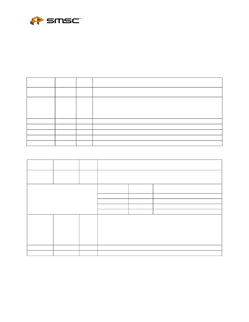
Table 4.1 - System Interface Signals
NAME
BUFFER
TYPE
IS
ACTIVE
LEVEL
Low
DESCRIPTION
RESET_N
Chip Reset
. The minimum active low pulse is 100ns. See section 8.4 for a
complete description of operation following a reset.
Self-power Detect
. Detects availability of local self-power source:
0: Self/local power source is NOT available (i.e., 4- Port Hub gets all power
from Upstream USB V
BUS
).
1: Self/local power source is available.
Test Pin.
Do Not Connect
Test Pin.
Do Not Connect
Test Pin.
Do Not Connect
Test Pin.
Do Not Connect
Test Pin.
Do Not Connect
SELF_PWR
I
High
TEST_P0
TEST_P1
TEST_P2
TEST_P3
ATEST
IPD
IPD
IPD
IPD
AO
N/A
N/A
N/A
N/A
N/A
Table 4.2 – Configuration Select and Serial Port Interface
NAME
BUFFER
TYPE
I
ACTIVE
LEVEL
N/A
DESCRIPTION
SMB_SEL_N
SMBus Select
. Selects between configuration via the SMBus interface, or
from an external EEPROM or using the internal default, as described in
the table below.
SMB_SEL_N
CS/EE_SEL
SMBus or EEPROM interface
configuration.
SMBus slave. Address: 0101100
SMBus slave. Address: 0101101
Internal default configuration.
2-wire EEPROM interface.
0
0
1
1
0
1
0
1
CS/EE_SEL
IO8
N/A
Chip Select
. This multifunction pin is sampled on the rising edge of
RESET_N. If SMB_SEL_N = 1, the internal default configuration will be
used when this pin is low, or the external I2C EEPROM will supply the
configuration when this pin is high. When SMB_SEL_N = 0, this pin
selects the SMBus slave address, as described in the table above.
Connect a 1k ohm resistor in series with the input when connecting this
pin to either VDD or VSS.
Serial Data
. Data I/O on the 2-Wire interface.
Serial Clock
. Clock for the 2-Wire interface.
SD/SDA
SCK/SCL
IOSD12
IOSD12
N/A
N/A
相關(guān)PDF資料 |
PDF描述 |
|---|---|
| 20N60BD1 | HiPerFAST IGBT with Diode |
| 20N60B | HiPerFAST IGBT |
| 20S207DA4 | VACUUM FLUORESCENT DISPLAY MODULE |
| 20SVP150M | OS-CON SVP series |
| 20SVP22M | SVP series |
相關(guān)代理商/技術(shù)參數(shù) |
參數(shù)描述 |
|---|---|
| 20H07-660 | 功能描述:保險絲 20AMP 660VAC/250VDC RoHS:否 制造商:Littelfuse 產(chǎn)品:Surface Mount Fuses 電流額定值:0.5 A 電壓額定值:600 V 保險絲類型:Fast Acting 保險絲大小/組:Nano 尺寸:12.1 mm L x 4.5 mm W 安裝風格: 端接類型:SMD/SMT 系列:485 |
| 20H07C | 功能描述:保險絲 20A CANADIAN RoHS:否 制造商:Littelfuse 產(chǎn)品:Surface Mount Fuses 電流額定值:0.5 A 電壓額定值:600 V 保險絲類型:Fast Acting 保險絲大小/組:Nano 尺寸:12.1 mm L x 4.5 mm W 安裝風格: 端接類型:SMD/SMT 系列:485 |
| 20H07CB | 制造商:未知廠家 制造商全稱:未知廠家 功能描述:Fuse |
| 20H18A | 制造商: 功能描述: 制造商:TE Connectivity / Deutsch 功能描述: 制造商:undefined 功能描述: |
| 20H-20F | 制造商:Panasonic Industrial Company 功能描述:CABLE |
發(fā)布緊急采購,3分鐘左右您將得到回復。