- 您現(xiàn)在的位置:買賣IC網(wǎng) > PDF目錄384074 > 1H1 (Won-Top Electronics Co., Ltd.) 1.0A ULTRAFAST DIODE PDF資料下載
參數(shù)資料
| 型號: | 1H1 |
| 廠商: | Won-Top Electronics Co., Ltd. |
| 英文描述: | 1.0A ULTRAFAST DIODE |
| 中文描述: | 安培超快二極管 |
| 文件頁數(shù): | 1/4頁 |
| 文件大小: | 52K |
| 代理商: | 1H1 |
1H1 – 1H8
1 of 4 2006 Won-Top Electronics
Pb
1H1 – 1H8
1.0A ULTRAFAST DIODE
Features
!
Diffused Junction
!
Low Forward Voltage Drop
!
High Current Capability A B A
!
High Reliability
!
High Surge Current Capability
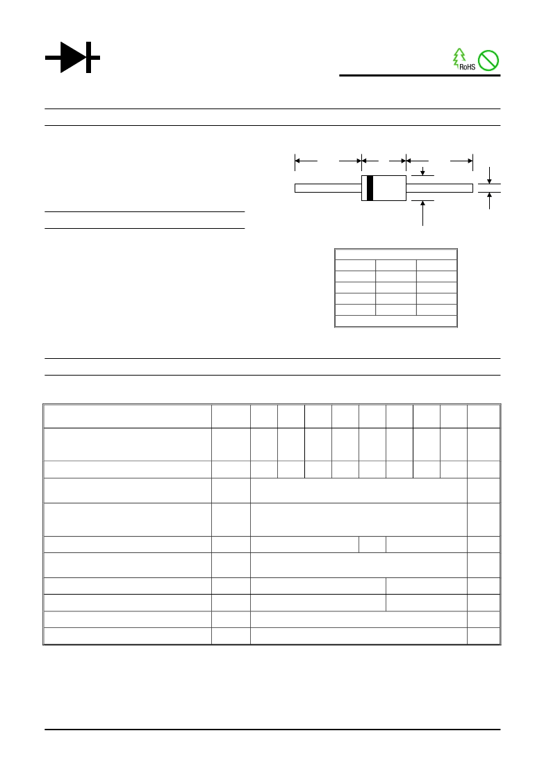
Mechanical Data
C
!
Case: R-1, Molded Plastic D
!
Terminals: Plated Leads Solderable per
MIL-STD-202, Method 208
!
Polarity: Cathode Band
!
Weight: 0.181
grams (approx.)
!
Mounting Position: Any
!
Marking: Type Number
!
Lead Free: For RoHS / Lead Free Version,
Add “-LF” Suffix to Part Number, See Page 4
Maximum Ratings and Electrical Characteristics
@T
A
=25°C unless otherwise specified
Single Phase, half wave, 60Hz, resistive or inductive load.
For capacitive load, derate current by 20%.
Characteristic
Symbol
1H1
1H2
1H3
1H4
1H5
1H6
1H7
1H8
Unit
Peak Repetitive Reverse Voltage
Working Peak Reverse Voltage
DC Blocking Voltage
V
RRM
V
RWM
V
R
50
100
200
300
400
600
800
1000
V
RMS Reverse Voltage
V
R(RMS)
35
70
140
210
280
420
560
700
V
Average Rectified Output Current
(Note 1) @T
A
= 55°C
I
O
1.0
A
Non-Repetitive Peak Forward Surge Current
8.3ms Single half sine-wave superimposed on
rated load (JEDEC Method)
I
FSM
30
A
Forward Voltage @I
F
= 1.0A
V
FM
1.0
1.3
1.7
V
Peak Reverse Current @T
= 25°C
At Rated DC Blocking Voltage @T
A
= 100°C
I
RM
5.0
100
μA
Reverse Recovery Time (Note 2)
t
rr
50
75
nS
Typical Junction Capacitance (Note 3)
C
j
20
15
pF
Operating Temperature Range
T
j
-65 to +125
°C
Storage Temperature Range
T
STG
-65 to +150
°C
Note: 1. Leads maintained at ambient temperature at a distance of 9.5mm from the case
2. Measured with IF = 0.5A, IR = 1.0A, IRR = 0.25A. See figure 5.
3. Measured at 1.0 MHz and applied reverse voltage of 4.0V D.C.
WTE
POWER SEMICONDUCTORS
R-1
Min
20.0
2.90
0.53
2.20
Dim
A
B
C
D
Max
—
3.50
0.64
2.60
All Dimensions in mm
相關(guān)PDF資料 |
PDF描述 |
|---|---|
| 1H1_06 | 1.0A ULTRAFAST DIODE |
| 1H2 | 1.0A ULTRAFAST DIODE |
| 1H3 | 1.0A ULTRAFAST DIODE |
| 1H4 | 1.0A ULTRAFAST DIODE |
| 1H5 | 1.0A ULTRAFAST DIODE |
相關(guān)代理商/技術(shù)參數(shù) |
參數(shù)描述 |
|---|---|
| 1H1_06 | 制造商:WTE 制造商全稱:Won-Top Electronics 功能描述:1.0A ULTRAFAST DIODE |
| 1H1_13 | 制造商:MCC 制造商全稱:Micro Commercial Components 功能描述:1.0 Amp High Efficient Rectifier 50 - 1000 Volts |
| 1H-10 | 制造商:Olympic Controls Corporation 功能描述: |
| 1H102JF | 制造商: 功能描述: 制造商:undefined 功能描述: |
| 1H102MCA | 制造商: 功能描述: 制造商:undefined 功能描述: |
發(fā)布緊急采購,3分鐘左右您將得到回復。