- 您現(xiàn)在的位置:買賣IC網(wǎng) > PDF目錄361484 > TK15405 (TOKO Inc.) OPERATIONAL AMPLIFIER WITH 75 OHM DRIVER PDF資料下載
January 2000 TOKO, Inc.
Page 3
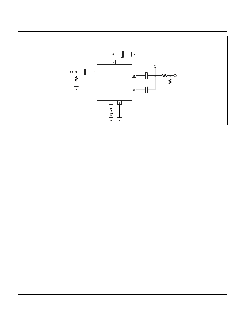
TK15405
75
+
33 μF
33 μF
75
VCC
+
VCC = 5.0 V
4.7 μF
+
75
Standby
GND
+Input
TP1
Output
VOUT = 2.0 VP-P
+
33 μF
TP2
TP3
TEST CIRCUIT
MEASUREMENT METHOD
1. Supply Current (I
)
The Pin 6 current is measured with no input signal and the Standby Pin (Pin 1) open.
2. Standby Supply Current (I
)
The Pin 6 current is measured when the Standby Pin (Pin 1) is connected to ground.
3. Standby Terminal Current (I
)
The Pin 1 current is measured when Pin 1 is connected to ground.
4. Threshold Voltage (High to Low) (V
)
The Pin 1 voltage is measured at the point which changes the device from operating mode into standby mode.
5. Threshold Voltage (Low to High) (V
)
The Pin 1 voltage is measured at the point which changes the device from standby mode into operating mode.
6. Clamp Voltage (V
)
The DC voltage at Pin 4 is measured with no input signal.
7. Voltage Gain (GVA)
The voltage gain equation is as follows:
GVA = 20 log
V2/V1
Where V1 is the input voltage at TP1 and V2 is the measured output voltage at TP2.
8. Differential Gain (DG)
The differential gain is measured at TP3 when a staircase waveform of 10 steps is applied to TP1.
9. Differential Phase (DP)
The differential phase is measured at TP3 when a staircase waveform of 10 steps is applied to TP1.
10. Frequency Response (fr)
The frequency response equation is as follows:
fr = 20 log
V2/V1
Where V1 is the measured TP3 voltage when the TP1 input frequency is set to 1 MHz and V2 is the measured TP3 voltage
when the TP1 input frequency is set to 5 MHz.
相關(guān)PDF資料 |
PDF描述 |
|---|---|
| TK15405M | OPERATIONAL AMPLIFIER WITH 75 OHM DRIVER |
| TK15405MTL | OPERATIONAL AMPLIFIER WITH 75 OHM DRIVER |
| TK15406 | 75 OHM VIDEO LINE DRIVER |
| TK15406M | 75 OHM VIDEO LINE DRIVER |
| TK15406MTL | 75 OHM VIDEO LINE DRIVER |
相關(guān)代理商/技術(shù)參數(shù) |
參數(shù)描述 |
|---|---|
| TK15405M | 制造商:TOKO 制造商全稱:TOKO, Inc 功能描述:OPERATIONAL AMPLIFIER WITH 75 OHM DRIVER |
| TK15405MTL | 制造商:TOKO 制造商全稱:TOKO, Inc 功能描述:OPERATIONAL AMPLIFIER WITH 75 OHM DRIVER |
| TK15405MTL/405 | 制造商:TOKO 制造商全稱:TOKO, Inc 功能描述:OPERATIONAL AMPLIFIER WITH 75 OHM DRIVER |
| TK15406 | 制造商:TOKO 制造商全稱:TOKO, Inc 功能描述:75 OHM VIDEO LINE DRIVER |
| TK15406M | 制造商:TOKO 制造商全稱:TOKO, Inc 功能描述:75 OHM VIDEO LINE DRIVER |
發(fā)布緊急采購,3分鐘左右您將得到回復(fù)。