- 您現(xiàn)在的位置:買賣IC網(wǎng) > PDF目錄372303 > ST52F514F3M6 IC MAX 7000 CPLD 256 256-FBGA PDF資料下載
參數(shù)資料
| 型號(hào): | ST52F514F3M6 |
| 英文描述: | IC MAX 7000 CPLD 256 256-FBGA |
| 中文描述: | 微控制器 |
| 文件頁數(shù): | 91/106頁 |
| 文件大小: | 648K |
| 代理商: | ST52F514F3M6 |
第1頁第2頁第3頁第4頁第5頁第6頁第7頁第8頁第9頁第10頁第11頁第12頁第13頁第14頁第15頁第16頁第17頁第18頁第19頁第20頁第21頁第22頁第23頁第24頁第25頁第26頁第27頁第28頁第29頁第30頁第31頁第32頁第33頁第34頁第35頁第36頁第37頁第38頁第39頁第40頁第41頁第42頁第43頁第44頁第45頁第46頁第47頁第48頁第49頁第50頁第51頁第52頁第53頁第54頁第55頁第56頁第57頁第58頁第59頁第60頁第61頁第62頁第63頁第64頁第65頁第66頁第67頁第68頁第69頁第70頁第71頁第72頁第73頁第74頁第75頁第76頁第77頁第78頁第79頁第80頁第81頁第82頁第83頁第84頁第85頁第86頁第87頁第88頁第89頁第90頁當(dāng)前第91頁第92頁第93頁第94頁第95頁第96頁第97頁第98頁第99頁第100頁第101頁第102頁第103頁第104頁第105頁第106頁
ST52F510/F513/F514
91/106
14.5 Register Description
In the following sections describe the registers
used by the I
2
C Interface are described.
14.5.1 I
2
C Interface Configuration Registers.
I
2
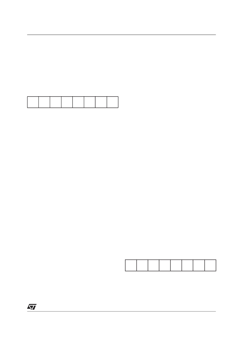
C Control Register (I2C_CR)
Configuration Register 16 (010h) Read/Write
Reset Value: 0000 0000 (00h)
Bit 7-6: Not Used
Bit 5:
PE
Peripheral Enable.
This bit is set and cleared by software
0: peripheral disabled
1: peripheral enabled
Notes:
– When PE=0, all the bits of the I2C_CR register
and the SR registerexcept theStop bit are reset.
All outputs are released while PE=0
– When PE=1, the corresponding I/O pins are se-
lected by hardware as alternate functions.
– To enable the I
2
C interface, write the I2C_CR
register
TWICE
with PE=1 as the first write only
activates the interface (only PE is set).
Bit 4:
ENGC
Enable General Call
This bit is set and cleared by software. It is
also cleared by hardware when the interface
is disabled (PE=0).
0: General Call disabled
1: General Call enabled
Note:
acknowledged (01h ignored).
The
00h
General
Call
address
is
Bit 3:
START
Generation of a Start Condition
This bit is set and cleared by software. It is
also cleared by hardware when the interface
is disabled (PE=0) or when
condition is sent (with interrupt generation if
ITE=1).
the Start
– In Master Mode
0: No Start generation
1: Repeated Start generation
– In Slave Mode
0: No Start generation
1: Start generation when the bus is free
Bit 2:
ACK
Acknowledge enable
This bit is set and cleared by software. It is
also cleared by hardware when the interface
is disabled (PE=0).
0: No acknowledge returned
1: Acknowledge returned after an address
byte or a data byte is received
Bit 1:
STOP
Reset signal mode
This bit is set and cleared by software. It is
also cleared by hardware in master mode.
Note: This bit is not cleared when the
interface is disabled (PE=0).
– In Master Mode
0: No Stop generation
1: Stop generation after the current byte
transfer or afterthe current Start condition
is sent. The STOP bit is cleared by
hardware when the Stop condition is sent.
– In Slave Mode
0: No Start generation
1: Release the SCL and SDA lines after the
current byte transfer (BTF=1). In this
mode the STOP bit has to be cleared by
software.
Bit 0:
ITE
Interrupt Enable
0: Interrupt disabled
1: Interrupt enabled
I
2
C Clock Control Register (I2C_CCR)
Configuration Register 17 (011h) Read/Write
Reset Value: 0000 0000 (00h)
Bit 7:
FM/SM
Fast/Standard I
2
C Mode.
This bit is set and cleared by software. It is
not cleared when the interface is disabled
(PE=0).
7
0
-
-
PE
ENGC
START
ACK
STOP
ITE
7
0
FM/SM
CC6
CC5
CC4
CC3
CC2
CC1
CC0
相關(guān)PDF資料 |
PDF描述 |
|---|---|
| ST52F514G0B6 | IC MAX 7000 CPLD 256 256-FBGA |
| ST52F514G0M6 | IC MAX 7000 CPLD 64 100-TQFP |
| ST52F514G1B6 | IC MAX 7000 CPLD 64 100-TQFP |
| ST52F514G1M6 | IC MAX 7000 CPLD 64 44-PLCC |
| ST52F514G3B6 | IC MAX 7000 CPLD 64 44-TQFP |
相關(guān)代理商/技術(shù)參數(shù) |
參數(shù)描述 |
|---|---|
| ST52F514FMB6 | 制造商:STMICROELECTRONICS 制造商全稱:STMicroelectronics 功能描述:8-BIT INTELLIGENT CONTROLLER UNIT ICU Two Timer/PWMs, ADC, I2C, SPI, SCI |
| ST52F514FMM6 | 制造商:STMICROELECTRONICS 制造商全稱:STMicroelectronics 功能描述:8-BIT INTELLIGENT CONTROLLER UNIT ICU Two Timer/PWMs, ADC, I2C, SPI, SCI |
| ST52F514G0B6 | 制造商:未知廠家 制造商全稱:未知廠家 功能描述:Microcontroller |
| ST52F514G0M6 | 制造商:未知廠家 制造商全稱:未知廠家 功能描述:Microcontroller |
| ST52F514G1B6 | 制造商:未知廠家 制造商全稱:未知廠家 功能描述:Microcontroller |
發(fā)布緊急采購,3分鐘左右您將得到回復(fù)。