- 您現(xiàn)在的位置:買賣IC網(wǎng) > PDF目錄372303 > ST52F514F1M6 IC MAX 7000 CPLD 256 208-PQFP PDF資料下載
參數(shù)資料
| 型號(hào): | ST52F514F1M6 |
| 英文描述: | IC MAX 7000 CPLD 256 208-PQFP |
| 中文描述: | 微控制器 |
| 文件頁數(shù): | 85/106頁 |
| 文件大?。?/td> | 648K |
| 代理商: | ST52F514F1M6 |
第1頁第2頁第3頁第4頁第5頁第6頁第7頁第8頁第9頁第10頁第11頁第12頁第13頁第14頁第15頁第16頁第17頁第18頁第19頁第20頁第21頁第22頁第23頁第24頁第25頁第26頁第27頁第28頁第29頁第30頁第31頁第32頁第33頁第34頁第35頁第36頁第37頁第38頁第39頁第40頁第41頁第42頁第43頁第44頁第45頁第46頁第47頁第48頁第49頁第50頁第51頁第52頁第53頁第54頁第55頁第56頁第57頁第58頁第59頁第60頁第61頁第62頁第63頁第64頁第65頁第66頁第67頁第68頁第69頁第70頁第71頁第72頁第73頁第74頁第75頁第76頁第77頁第78頁第79頁第80頁第81頁第82頁第83頁第84頁當(dāng)前第85頁第86頁第87頁第88頁第89頁第90頁第91頁第92頁第93頁第94頁第95頁第96頁第97頁第98頁第99頁第100頁第101頁第102頁第103頁第104頁第105頁第106頁
ST52F510/F513/F514
85/106
14 I
2
C BUS INTERFACE (I
2
C)
14.1 Introduction
The I
2
C Bus Interface serves as an interface
between the microcontroller and the serial I
2
C bus,
providing bothmultimaster and slave functions and
controls all I
2
C bus-specific sequencing, protocol,
arbitration and timing. The
supports fast I
2
C mode (400kHz).
I
2
Bus Interface
14.2 Main Features
I
Parallel-bus/I
2
C protocol converter
I
Multi-master capability
I
7-bit/10-bit Addressing
I
Transmitter/Receiver flag
I
End-of-byte transmission flag
I
Transfer problem detection
I
2
C Master Features:
I
Clock generation
I
I
2
C bus busy flag
I
Arbitration Lost Flag
I
End of byte transmission flag
I
Transmitter/Receiver Flag
I
Start bit detection flag
I
Start and Stop generation
I
2
C Slave Features:
I
Stop bit detection
I
I
2
C bus busy flag
I
Detection of misplaced start or stop condition
I
Programmable I
2
C Address detection
I
Transfer problem detection
I
End-of-byte transmission flag
I
Transmitter/Receiver flag
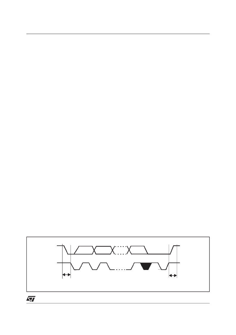
Figure 14.1 I
2
C BUS Protocol
14.3 General Description
In addition to receiving and transmitting data, this
interface converts it from serial to parallel format
and vice versa, using either an interrupt or polled
handshake. The interrupts are enabled or disabled
via software. The interface is connected to the I
2
C
bus by a data pin (SDA) and by a clock pin (SCL).
The interface can be connected both with a
standard I
2
C bus and a Fast I
2
C bus. This
selection is made via software.
14.3.1 Mode Selection.
The interface can operate in the following four
modes:
– Slave transmitter/receiver
– Master transmitter/receiver
By default, it operates in slave mode.
The interface automatically switches from slave to
master after it generates a START condition and
from master to slave incase of arbitration loss ora
STOP
generation,
providing
capability.
Multi-Master
14.3.2 Communication Flow.
In Master mode, Communication Flow initiates
data transfer and generates the clock signal. A
serial data transfer always begins with a start
condition and ends with a stopcondition. Both start
and stopconditions are generated in master mode
by software.
In Slave mode the interface is capable of
recognizing its own address (7 or 10-bit) and the
General Call address. The General Call address
detection may be enabled or disabled bysoftware.
Data and addresses are transferred as 8-bit bytes,
(MSB first). The first byte(s) follow the start
condition is the address (one in 7-bit mode, two in
10-bit mode), which is always transmitted in
Master mode.A 9th clock pulse follows the 8 clock
cycles of a byte transfer, during which the receiver
must send an acknowledge bit to the transmitter.
Refer to Figure 14.1.
SCL
SDA
1
2
8
9
MSB
ACK
STOP
CONDITION
START
CONDITION
相關(guān)PDF資料 |
PDF描述 |
|---|---|
| ST52F514F3B6 | IC MAX 7000 CPLD 256 208-PQFP |
| ST52F514F3M6 | IC MAX 7000 CPLD 256 256-FBGA |
| ST52F514G0B6 | IC MAX 7000 CPLD 256 256-FBGA |
| ST52F514G0M6 | IC MAX 7000 CPLD 64 100-TQFP |
| ST52F514G1B6 | IC MAX 7000 CPLD 64 100-TQFP |
相關(guān)代理商/技術(shù)參數(shù) |
參數(shù)描述 |
|---|---|
| ST52F514F3B6 | 制造商:未知廠家 制造商全稱:未知廠家 功能描述:Microcontroller |
| ST52F514F3M6 | 制造商:未知廠家 制造商全稱:未知廠家 功能描述:Microcontroller |
| ST52F514FMB6 | 制造商:STMICROELECTRONICS 制造商全稱:STMicroelectronics 功能描述:8-BIT INTELLIGENT CONTROLLER UNIT ICU Two Timer/PWMs, ADC, I2C, SPI, SCI |
| ST52F514FMM6 | 制造商:STMICROELECTRONICS 制造商全稱:STMicroelectronics 功能描述:8-BIT INTELLIGENT CONTROLLER UNIT ICU Two Timer/PWMs, ADC, I2C, SPI, SCI |
| ST52F514G0B6 | 制造商:未知廠家 制造商全稱:未知廠家 功能描述:Microcontroller |
發(fā)布緊急采購,3分鐘左右您將得到回復(fù)。