- 您現(xiàn)在的位置:買賣IC網(wǎng) > PDF目錄374857 > SN54LVCH245AFK (Texas Instruments, Inc.) OCTAL BUS TRANSCEIVERS WITH 3-STATE OUTPUTS PDF資料下載
參數(shù)資料
| 型號: | SN54LVCH245AFK |
| 廠商: | Texas Instruments, Inc. |
| 英文描述: | OCTAL BUS TRANSCEIVERS WITH 3-STATE OUTPUTS |
| 中文描述: | 八路總線收發(fā)器與三態(tài)輸出 |
| 文件頁數(shù): | 3/9頁 |
| 文件大小: | 127K |
| 代理商: | SN54LVCH245AFK |
SN54LVCH245A, SN74LVCH245A
OCTAL BUS TRANSCEIVERS
WITH 3-STATE OUTPUTS
SCES008F – JULY 1995 - REVISED JUNE 1998
3
POST OFFICE BOX 655303
DALLAS, TEXAS 75265
absolute maximum ratings over operating free-air temperature range (unless otherwise noted)
Supply voltage range, V
CC
Input voltage range, V
I
:(see Note 1)
Voltage range applied to any output in the high-impedance or power-off state, V
O
(see Note 1)
. . . . . . . . . . . . . . . . . . . . . . . . . . . . . . . . . . . . . . . . . . . . . . . . . . . . . . . . . . . . . . . . . . .
Voltage range applied to any output in the high or low state, V
O
(see Notes 1 and 2)
. . . . . . . . . . . . . . . . . . . . . . . . . . . . . . . . . . . . . . . . . . . . . . . . . . . . . . .
Input clamp current, I
IK
(V
I
< 0)
. . . . . . . . . . . . . . . . . . . . . . . . . . . . . . . . . . . . . . . . . . . . . . . . . . . . . . . . . . .
Output clamp current, I
OK
(V
O
< 0)
. . . . . . . . . . . . . . . . . . . . . . . . . . . . . . . . . . . . . . . . . . . . . . . . . . . . . . . .
Continuous output current, I
O
. . . . . . . . . . . . . . . . . . . . . . . . . . . . . . . . . . . . . . . . . . . . . . . . . . . . . . . . . . . . .
Continuous current through V
CC
or GND
. . . . . . . . . . . . . . . . . . . . . . . . . . . . . . . . . . . . . . . . . . . . . . . . . .
Package thermal impedance,
θ
JA
(see Note 3): DB package
DW package
PW package
Storage temperature range, T
stg
. . . . . . . . . . . . . . . . . . . . . . . . . . . . . . . . . . . . . . . . . . . . . . . . . . .
Stresses beyond those listed under “absolute maximum ratings” may cause permanent damage to the device. These are stress ratings only, and
functional operation of the device at these or any other conditions beyond those indicated under “recommended operating conditions” is not
implied. Exposure to absolute-maximum-rated conditions for extended periods may affect device reliability.
NOTES:
1. The input negative-voltage and output voltage ratings may be exceeded if the input and output current ratings are observed.
2. The value of VCC is provided in the recommended operating conditions table.
3. The package thermal impedance is calculated in accordance with JESD 51.
–0.5 V to 6.5 V
–0.5 V to 6.5 V
. . . . . . . . . . . . . . . . . . . . . . . . . . . . . . . . . . . . . . . . . . . . . . . . . . . . . . . . .
. . . . . . . . . . . . . . . . . . . . . . . . . . . . . . . . . . . . . . . . . . . . . . . . .
–0.5 V to 6.5 V
–0.5 V to V
CC
+ 0.5 V
–50 mA
–50 mA
±
50 mA
±
100 mA
115
°
C/W
97
°
C/W
128
°
C/W
. . . . . . . . . . . . . . . . . . . . . . . . . . . . . . . .
. . . . . . . . . . . . . . . . . . . . . . . . . . . . . . . . .
. . . . . . . . . . . . . . . . . . . . . . . . . . . . . . . .
–65
°
C to 150
°
C
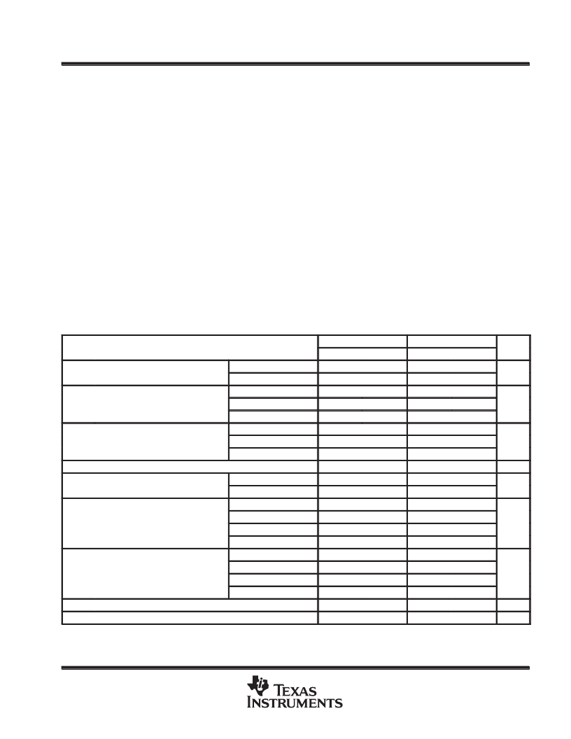
recommended operating conditions (see Note 4)
SN54LVCH245A
MIN
2
SN74LVCH245A
MIN
1.65
UNIT
MAX
3.6
MAX
3.6
VCC
Supply voltage
Operating
V
Data retention only
1.5
1.5
VCC = 1.65 V to 1.95 V
VCC = 2.3 V to 2.7 V
VCC = 2.7 V to 3.6 V
VCC = 1.65 V to 1.95 V
VCC = 2.3 V to 2.7 V
VCC = 2.7 V to 3.6 V
0.65
×
VCC
1.7
VIH
High-level input voltage
V
2
2
0.35
×
VCC
0.7
VIL
Low-level input voltage
V
0.8
0.8
VI
Input voltage
0
5.5
0
5.5
V
VO
Output voltage
High or low state
0
VCC
5.5
0
VCC
5.5
V
3 state
0
0
VCC = 1.65 V
VCC = 2.3 V
VCC = 2.7 V
VCC = 3 V
VCC = 1.65 V
VCC = 2.3 V
VCC = 2.7 V
VCC = 3 V
–4
IOH
High level output current
High-level output current
–8
mA
–12
–12
–24
–24
4
IOL
Low level output current
Low-level output current
8
mA
12
12
24
24
t/
v
TA
NOTE 4: All unused control inputs of the device must be held at VCC or GND to ensure proper device operation. Refer to the TI application report,
Implications of Slow or Floating CMOS Inputs literature number SCBA004.
Input transition rise or fall rate
0
10
0
10
ns/V
°
C
Operating free-air temperature
–55
125
–40
85
相關(guān)PDF資料 |
PDF描述 |
|---|---|
| SN54LVCH245AJ | Analog Multiplexers/Demultiplexers; Package: SOEIAJ-16; No of Pins: 16; Container: Rail; Qty per Container: 50 |
| SN54LVCH245AW | Analog Multiplexers/Demultiplexers; Package: PDIP-16; No of Pins: 16; Container: Rail; Qty per Container: 500 |
| SN74LVCH245ADB | OCTAL BUS TRANSCEIVERS WITH 3-STATE OUTPUTS |
| SN54LVT162240 | Analog Multiplexers/Demultiplexers; Package: PDIP-16; No of Pins: 16; Container: Rail; Qty per Container: 500 |
| SN54LVT162244A | Analog Multiplexers/Demultiplexers; Package: SOIC 16 LEAD; No of Pins: 16; Container: Rail; Qty per Container: 48 |
相關(guān)代理商/技術(shù)參數(shù) |
參數(shù)描述 |
|---|---|
| SN54S00J | 制造商:Texas Instruments 功能描述:NAND Gate 4-Element 2-IN Bipolar 14-Pin CDIP Tube 制造商:Rochester Electronics LLC 功能描述:- Bulk |
| SN54S00W | 制造商:Rochester Electronics LLC 功能描述:- Bulk |
| SN54S02J | 制造商:Texas Instruments 功能描述: |
| SN54S03J | 制造商:Rochester Electronics LLC 功能描述:- Bulk 制造商:Texas Instruments 功能描述:2-INPUT NAND GATE (OC) - Rail/Tube |
| SN54S04J | 制造商:Texas Instruments 功能描述:Inverter 6-Element Bipolar 14-Pin CDIP Tube 制造商:Rochester Electronics LLC 功能描述:- Bulk 制造商:Texas Instruments 功能描述:INVERTER 6-ELEM BIPOLAR 14CDIP - Rail/Tube 制造商:Texas Instruments 功能描述:HEX INVERTER *NIC* |
發(fā)布緊急采購,3分鐘左右您將得到回復(fù)。