- 您現(xiàn)在的位置:買賣IC網(wǎng) > PDF目錄374805 > SL523CCM (ZARLINK SEMICONDUCTOR INC) 100MHz DUAL WIDEBAND LOG AMPLIFIER PDF資料下載
參數(shù)資料
| 型號: | SL523CCM |
| 廠商: | ZARLINK SEMICONDUCTOR INC |
| 元件分類: | 運動控制電子 |
| 英文描述: | 100MHz DUAL WIDEBAND LOG AMPLIFIER |
| 中文描述: | LOG OR ANTILOG AMPLIFIER, 90 MHz BAND WIDTH, MBCY8 |
| 封裝: | CM-8 |
| 文件頁數(shù): | 4/9頁 |
| 文件大小: | 362K |
| 代理商: | SL523CCM |
SL523
ELECTRICAL CHARACTERISTICS
These characteristics are guaranteed over the following condltions (unless otherwise stated)
Ambient temperature = 22
°
C
±
2
°
C; Source impedance = 10
; Supply voltage = +6V; Load impedance = 8pF;
Frequency = 60MHz; DC connection between Pin 6 and 7
Min.
Typ.
Max.
Small signal voltage gain
B
C
B
C
22.6
22
22
21.4
24
24
24
24
0.5
150
10
4
2.1
2.1
1.9
25.4
26
26
26.6
0.75
dB
dB
dB
dB
dB
MHz
MHz
ns
mA
mA
V RMS
Small signal voltage gain
Gain variation (set of 8)
Upper cut-off frequency
Lower cut-off frequency
Propagation delay
Maximum rectified video
output current
Maximum input signal before
overload
Noise figure
Supply current
Frequency = 60MHz
B, C
B, C
B, C
B
C
B, C
120
15
1.9
1.8
1.8
2.3
2.4
See note below
4
30
30
1.2
5.25
36
38
dB
mA
mA
V p-p
Source impedance 450
B
C
B, C
25
23
Maximum RF output voltage
Value
Units
Conditions
Circuits
Characteristic
Frequency = 30MHz
Frequency = 60MHz
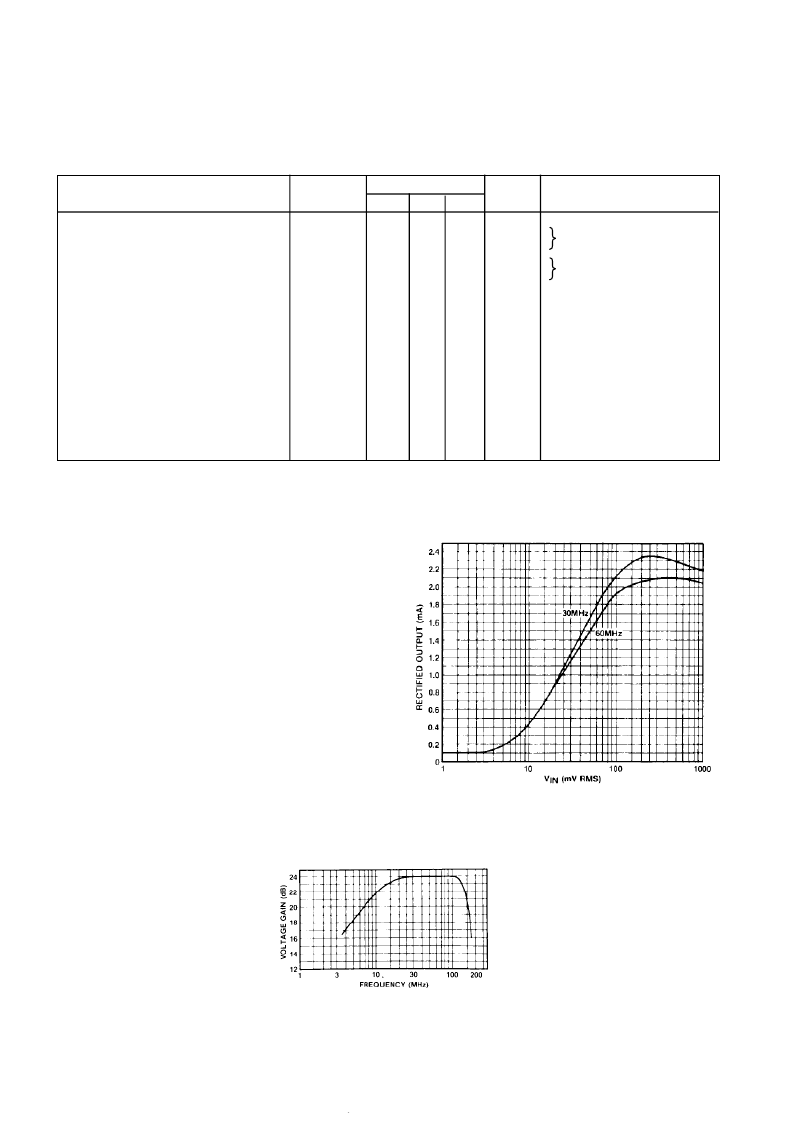
Fig.4 Voltage gain v. frequency (typical)
OPERATING NOTES
The amplifier is designed to be directly coupled (seeFig.5)
The fourth stage in an untuned cascade will give full output
on the broad band noise generated by the first stage.
Noise may be reduced by inserting a single tuned circuit in
the chain As there is a large mismatch between stages a
simple shunt or series circuit cannot be used The network
chosen must give unity voltage gain at resonance to avoid
distorting the log law The typical value for input impedance is
500
in parallel with 5pF and the output impedance is typically
30
.
Although a 1nF supply line decoupling capacitor is
included in the can an extra capacitor is required when the
amplifiers are cascaded Minimum values for this capacitor
are: 2 stages - 3nF, 3 or more stages 30nF
In cascades of 3 or more stages care must be taken to
avoid oscillations caused either by inductance common to the
input and output earths of the strip or by feedback along the
common video line The use of a continuous earth plane will
avoid earth inductance problems and a common base
amplifier in the video line isolating the first two stages as
shown in Fig 6 will eliminate feedback on the video line
Fig.3 Rectified output current v. input signal (typical)
Note:- Overload occurs when the input signal reaches a level sufficient to forward bias the base-collector junction to the input
transistor on peaks
相關(guān)PDF資料 |
PDF描述 |
|---|---|
| SL541 | HIGH SLEW RATE OPERATIONAL AMPLIFIER |
| SL541BCM | HIGH SLEW RATE OPERATIONAL AMPLIFIER |
| SL541BDG | HIGH SLEW RATE OPERATIONAL AMPLIFIER |
| SL541NAIC | HIGH SLEW RATE OPERATIONAL AMPLIFIER |
| SL560 | 300MHz LOW NOISE AMPLIFIER |
相關(guān)代理商/技術(shù)參數(shù) |
參數(shù)描述 |
|---|---|
| SL5240 | 制造商:SURGE 制造商全稱:Surge Components 功能描述:SILICON PLANAR ZENER DIODES, 500mW,MINIMELF PACKAGE |
| SL5241 | 制造商:SURGE 制造商全稱:Surge Components 功能描述:SILICON PLANAR ZENER DIODES, 500mW,MINIMELF PACKAGE |
| SL5242 | 制造商:SURGE 制造商全稱:Surge Components 功能描述:SILICON PLANAR ZENER DIODES, 500mW,MINIMELF PACKAGE |
| SL5243 | 制造商:SURGE 制造商全稱:Surge Components 功能描述:SILICON PLANAR ZENER DIODES, 500mW,MINIMELF PACKAGE |
| SL5244 | 制造商:SURGE 制造商全稱:Surge Components 功能描述:SILICON PLANAR ZENER DIODES, 500mW,MINIMELF PACKAGE |
發(fā)布緊急采購,3分鐘左右您將得到回復(fù)。