- 您現(xiàn)在的位置:買賣IC網(wǎng) > PDF目錄374796 > SK10EL16TBDT (Semtech Corporation) Differential Receiver PDF資料下載
參數(shù)資料
| 型號: | SK10EL16TBDT |
| 廠商: | Semtech Corporation |
| 英文描述: | Differential Receiver |
| 中文描述: | 差分接收器 |
| 文件頁數(shù): | 7/10頁 |
| 文件大小: | 201K |
| 代理商: | SK10EL16TBDT |
+
Revision 1/February 12, 2001
,
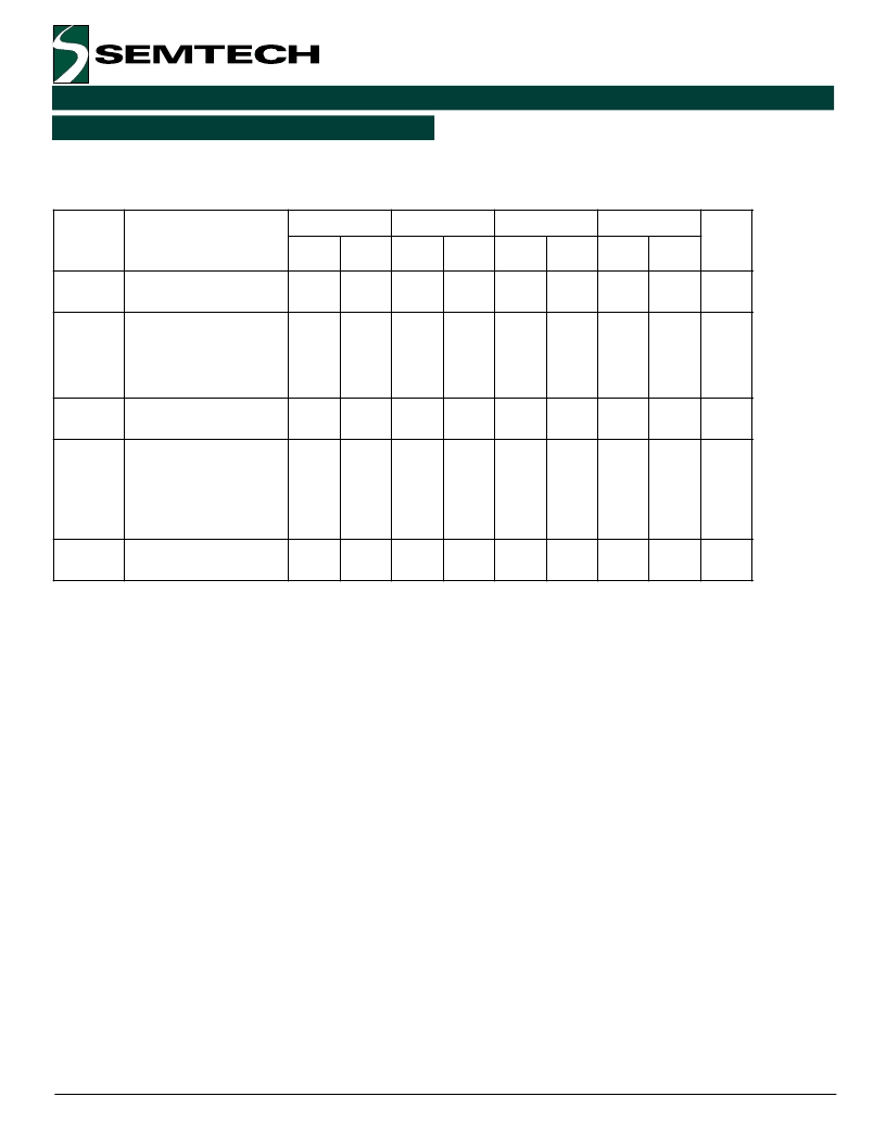
(V
CC
– V
EE
= 3.0V to 5.5V)
SK10/100EL16TA-TD AC Electrical Characteristics
3
.
-
#
.
.
3
5
4
6
*
7
&
1
)
&
&
)
,
,
*
-
-
-
-
'
'
'
'
'
'
#
#
'
#
"
'
"
#
"
"
!
"
'
#
!
+
8
+
8
%
*
6
*
:
9
.
-
;
9
;
"
:
-
-
-
-
'
'
'
'
!
"
!
!
!
"
!
!
!
!
"
!
'
!
"
'
4
<
4
.
.
$
$
=
0
#
$
$
=
0
#
$
$
=
0
#
$
$
=
0
#
Notes:
1.
10EL circuits are designed to meet the DC specification shown in the table after thermal equilibrium has
been established. The circuit is in a test socket or mounted on a printed circuit board, and
transverse airflow greater than 500 lfpm is maintained.
100K circuits are designed to meet the DC specification shown in the table where transverse airflow
greater than 500 lfpm is maintained.
Duty cycle skew is the difference between T
PLH
and T
PHL
propagation delay through a device.
F
MAX
guaranteed for functionality only. See Figure 5 for typical output swing. VOL and VOH are
guaranteed at DC only.
Voltages referenced to VCC = 0V.
Minimum input swing for which parameters are guaranteed. The device has a DC gain of ~40.
CMR range is referenced to the most positive side of the differential input signal. Normal operation is
obtained if the high level falls within the specified range and the peak-to-peak voltage lies between
VPP
(min)
and 1V. The lower end of the CMR range varies 1:1 with VEE and is equal to VEE + 1.7V.
VO
P-P
is obtained as follows: Voltages of Q and Q* outputs with respect to VCC are measured. The
absolute difference between a high and a low state is equal to VO
pp
.
For standard ECL DC specifications, refer to the ECL Logic Family Standard DC Specifications Data
Sheet.
10. For part ordering description, see HPP Part Ordering Information Data Sheet.
2.
3.
4.
5.
6.
7.
8.
9.
TA = –40
o
C
TA = 0
o
C
TA = +25
o
C
TA = +85
o
C
相關PDF資料 |
PDF描述 |
|---|---|
| SK10EL16TDD | Differential Receiver |
| SK10EL16TDDT | Differential Receiver |
| SK10EL16TCD | Differential Receiver |
| SK10EL16TCDT | Differential Receiver |
| SK10EL16TU | Differential Receiver |
相關代理商/技術參數(shù) |
參數(shù)描述 |
|---|---|
| SK10EL16TCD | 制造商:SEMTECH 制造商全稱:Semtech Corporation 功能描述:Differential Receiver |
| SK10EL16TCDT | 制造商:SEMTECH 制造商全稱:Semtech Corporation 功能描述:Differential Receiver |
| SK10EL16TDD | 制造商:SEMTECH 制造商全稱:Semtech Corporation 功能描述:Differential Receiver |
| SK10EL16TDDT | 制造商:SEMTECH 制造商全稱:Semtech Corporation 功能描述:Differential Receiver |
| SK10EL16TU | 制造商:SEMTECH 制造商全稱:Semtech Corporation 功能描述:Differential Receiver |
發(fā)布緊急采購,3分鐘左右您將得到回復。