- 您現(xiàn)在的位置:買賣IC網(wǎng) > PDF目錄359234 > MT8985AP1 (ZARLINK SEMICONDUCTOR INC) Enhanced Digital Switch PDF資料下載
參數(shù)資料
| 型號: | MT8985AP1 |
| 廠商: | ZARLINK SEMICONDUCTOR INC |
| 元件分類: | 路由/交換 |
| 英文描述: | Enhanced Digital Switch |
| 中文描述: | TELECOM, DIGITAL TIME SWITCH, PQCC44 |
| 封裝: | LEAD FREE, PLASTIC, MS-018AC, LCC-44 |
| 文件頁數(shù): | 3/26頁 |
| 文件大?。?/td> | 568K |
| 代理商: | MT8985AP1 |
MT8985
Data Sheet
3
Zarlink Semiconductor Inc.
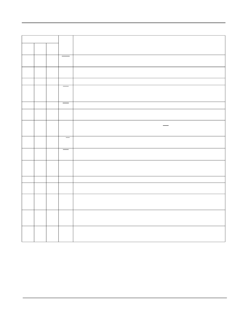
Pin Description
Pin #
Name
Description
40
DIP
44
PLCC
44
QFP
1
2
40
DTA
Data Acknowledgement
(Open Drain Output). This active low output indicates that
a data bus transfer is complete. A pull-up resistor is required at this output.
ST-BUS Input 0 to 7 (Inputs).
Serial data input streams. These streams have 32
channels at data rates of 2.048 Mbit/s.
2-9
3-5
7-11
41-43
1-5
STi0-
STi7
10
12
6
V
DD
+5 Volt Power Supply rail.
11
13
7
F0i
Frame Pulse (Input):
This input accepts and automatically identifies frame
synchronization signals formatted according to different backplane specifications
such as ST-BUS and GCI.
12
14
8
C4i
A0-A5
Address 0 to 5 (Inputs).
These lines provide the address to MT8985 internal
registers.
DS
Data Strobe (Input).
This is the input for the active high data strobe on the
microprocessor interface. This input operates with CS to enable the internal read and
write generation.
Clock (Input).
4.096 MHz serial clock for shifting data in and out of the data streams.
13-18 15-17
19-21
22
9-11
13-15
16
19
20
23
17
R/W
Read/Write (Input).
This input controls the direction of the data bus lines (D0-D7)
during a microprocessor access.
21
24
18
CS
Chip Select (Input).
Active low input enabling a microprocessor read or write of
control register or internal memories.
D7-D0
Data Bus 7 to 0 (Bidirectional).
These pins provide microprocessor access to data
in the internal control register, connect memory high, connect memory low and data
memory.
V
SS
Ground Rail.
STo7-
STo0
streams are composed of 32 channels at data rates of 2.048 Mbit/s.
ODE
Output Drive Enable (Input).
This is an output enable for the STo0 to STo7 serial
outputs. If this input is low STo0-7 are high impedance. If this input is high each
channel may still be put into high impedance by software control.
CSTo
Control ST-BUS Output (Output).
This output is a 2.048 Mb/s line which contains
256 bits per frame. The level of each bit is controlled by the contents of the CSTo bit
in the Connect Memory high locations.
NC
No Connection.
22-29 25-27
29-33
19-21
23-27
30
34
28
31-38 35-39
41-43
44
29-33
35-37
38
ST-BUS Outputs 7 to 0 (Three-state Outputs).
Serial data output streams. These
39
40
1
39
6, 18,
28,
40
12,22
34,
44
相關(guān)PDF資料 |
PDF描述 |
|---|---|
| MT8985 | CMOS ST-BUS⑩ FAMILY Enhanced Digital Switch |
| MT8985AE | CMOS ST-BUS⑩ FAMILY Enhanced Digital Switch |
| MT8985AL | CMOS ST-BUS⑩ FAMILY Enhanced Digital Switch |
| MT8985AP | CMOS ST-BUS⑩ FAMILY Enhanced Digital Switch |
| MT8985 | Enhanced Digital Switch |
相關(guān)代理商/技術(shù)參數(shù) |
參數(shù)描述 |
|---|---|
| MT8985APR | 制造商:Microsemi Corporation 功能描述: |
| MT8985APR1 | 制造商:Microsemi Corporation 功能描述:SWIT FABRIC 256 X 256 16.384MBPS 5V 44PLCC - Tape and Reel 制造商:MICROSEMI CONSUMER MEDICAL PRODUCT GROUP 功能描述:IC TDM/TSI SWITCH 256X256 44PLCC 制造商:Microsemi Corporation 功能描述:IC TDM/TSI SWITCH 256X256 44PLCC |
| MT8986 | 制造商:ZARLINK 制造商全稱:Zarlink Semiconductor Inc 功能描述:Multiple Rate Digital Switch |
| MT8986AC | 制造商:MITEL 制造商全稱:Mitel Networks Corporation 功能描述:CMOS ST-BUS⑩ FAMILY Multiple Rate Digital Switch |
| MT8986AE | 制造商:Microsemi Corporation 功能描述: |
發(fā)布緊急采購,3分鐘左右您將得到回復(fù)。