- 您現(xiàn)在的位置:買賣IC網(wǎng) > PDF目錄359201 > MPY534S Precision ANALOG MULTIPLIER PDF資料下載
參數(shù)資料
| 型號: | MPY534S |
| 英文描述: | Precision ANALOG MULTIPLIER |
| 中文描述: | 精密模擬乘法器 |
| 文件頁數(shù): | 5/8頁 |
| 文件大?。?/td> | 116K |
| 代理商: | MPY534S |
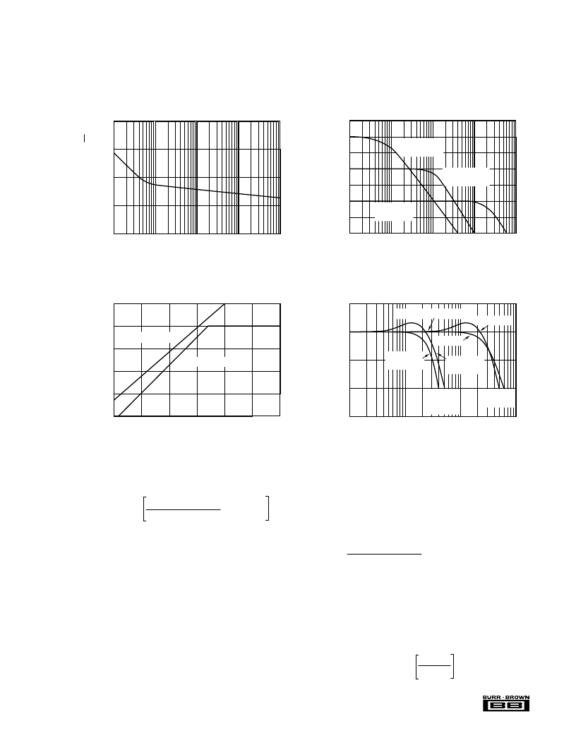
MPY534
5
10
0
–10
–20
–30
10k
100k
1M
10M
Frequency (Hz)
FREQUENCY RESPONSE AS A MULTIPLIER
O
C
L
= 0pF
C
L
≤
1000pF
C
F
= 0pF
With X10
Feedback
Attenuator
0dB = 0.1Vrms; R
L
= 2k
Normal
Connection
C
L
≤
1000pF
C
F
≤
200pF
C
L
= 1000pF
14
12
10
8
6
4
8
Positive or Negative Supply (V)
INPUT/OUTPUT SIGNAL RANGE
vs SUPPLY VOLTAGES
P
10
12
14
16
18
20
Output, R
L
≥
2k
All Inputs, SF = 10V
50
40
30
20
10
0
–10
–20
O
O
/
Z
1k
10k
1M
10M
Frequency (Hz)
FREQUENCY RESPONSE
vs DIVIDER DENOMINATOR INPUT VOLTAGE
100k
V
X
= 100mVDC
V
Z
= 10mVrms
V
X
= 10VDC
V
Z
= 1Vrms
V
X
= 1VDC
V
Z
= 100mVrms
1.5
1.25
1
0.75
0.5
10
100
10k
100k
Frequency (Hz)
NOISE SPECTRAL DENSITY
vs FREQUENCY
N
√
H
1k
TYPICAL PERFORMANCE CURVES
(CONT)
T
A
= +25
°
C,
±
V
CC
= 15VDC, unless otherwise noted.
THEORY OF OPERATION
The transfer function for the MPY534 is:
(X
– X
) (Y
– Y
)
V
OUT
= A – (Z
1
– Z
2
)
where:
A = Open-loop gain of the output amplifier
(typically 85dB at DC).
SF = Scale Factor. Laser-trimmed to 10V but
adjustable over a 3V to 10V range using
external resistor.
X, Y, A are input voltages. Full-scale input voltage
is equal to the selected SF. (Max input voltage =
±
1.25 SF.)
An intuitive understanding of transfer function can be gained
by analogy to an op amp. By assuming that the open-loop
gain, A, of the output amplifier is infinite, inspection of the
transfer function reveals that any V
OUT
can be created with
an infinitesimally small quantity within the brackets. Then,
SF
an application circuit can be analyzed by assigning circuit
voltages for all X, Y and Z inputs and setting the bracketed
quantity equal to zero. For example, the basic multiplier
connection in Figure 1, Z
= V
and Z
2
= 0. The quantity
within the brackets then reduces to:
(X
– X
) (Y
– Y
)
SF
– (V
OUT
– 0) = 0
This approach leads to a simple relationship which can be
solved for V
OUT
.
The scale factor is accurately factory-adjusted to 10V and is
typically accurate to within 0.1% or less. The scale factor
may be adjusted by connecting a resistor or potentiometer
between pin SF and the –V
S
power supply. The value of the
external resistor can be approximated by:
R
SF
= 5.4k
10 – SF
SF
相關(guān)PDF資料 |
PDF描述 |
|---|---|
| MPY534T | Precision ANALOG MULTIPLIER |
| MPY634 | Wide Bandwidth PRECISION ANALOG MULTIPLIER |
| MPY634AM | Wide Bandwidth PRECISION ANALOG MULTIPLIER |
| MPY634BM | Wide Bandwidth PRECISION ANALOG MULTIPLIER |
| MPY634KP | Wide Bandwidth PRECISION ANALOG MULTIPLIER |
相關(guān)代理商/技術(shù)參數(shù) |
參數(shù)描述 |
|---|---|
| MPY534SH | 制造商:Rochester Electronics LLC 功能描述:- Bulk |
| MPY534T | 制造商:BB 制造商全稱:BB 功能描述:Precision ANALOG MULTIPLIER |
| MPY534TD | 制造商:Rochester Electronics LLC 功能描述:I C MULTIPLIER - Bulk |
| MPY534TH | 制造商:Rochester Electronics LLC 功能描述:- Bulk |
| MPY5352K | 制造商:STANLEY 制造商全稱:STANLEY 功能描述:Single Color Rectangular Shape Type |
發(fā)布緊急采購,3分鐘左右您將得到回復(fù)。