- 您現在的位置:買賣IC網 > PDF目錄358849 > LM369BH (NATIONAL SEMICONDUCTOR CORP) Precision Voltage Reference PDF資料下載
參數資料
| 型號: | LM369BH |
| 廠商: | NATIONAL SEMICONDUCTOR CORP |
| 元件分類: | 基準電壓源/電流源 |
| 英文描述: | Precision Voltage Reference |
| 中文描述: | 1-OUTPUT THREE TERM VOLTAGE REFERENCE, 10 V, MBCY8 |
| 封裝: | METAL CAN-8 |
| 文件頁數: | 5/14頁 |
| 文件大?。?/td> | 262K |
| 代理商: | LM369BH |
Application Hints
The LM169/LM369 can be applied in the same way as any
other voltage reference. The adjacent Typical Applications
Circuits suggest various uses for the LM169/LM369. The
LM169 is recommended for applications where the highest
stability and lowest noise is required over the full military
temperature range. The LM369 is suitable for limited-tem-
perature operation. The curves showing the Noise vs. Ca-
pacitance in the Typical Performance Characteristics sec-
tion show graphically that a modest capacitance of 0.1 to
0.3 microfarads can cut the broadband noise down to a lev-
el of only a few microvolts, less than 1 ppm of the output
voltage. The capacitor used should be a low-leakage type.
For the temperature range 0 to 50
§
C, polyester or Mylar
é
will be suitable, but at higher temperatures, a premium film
capacitor such as polypropylene is recommended. For oper-
ation at
a
125
§
C, a Teflon
é
capacitor would be required, to
ensure sufficiently low leakage. Ceramic capacitors may
seem to do the job, but are not recommended for produc-
tion use, as the high-K ceramics cannot be guaranteed for
low leakage, and may exhibit piezo-electric effects, convert-
ing vibration or mechanical stress into excessive electrical
noise.
Additionally, the inherent superiority of the LM169/369’s
buried Zener diode provides freedom from low-frequency
noise, wobble, and jitter, in the frequency range 0.01 to 10
Hertz, where capacitive filtering is not feasible.
Pins 1, 3, 7, and 8 of the LM169/369 are connected to
internal trim circuits which are used to trim the device’s out-
put voltage and Tempco during final testing at the factory.
Do not connect anything to these pins, or improper opera-
tion may result. These pins would not be damaged by a
short to ground, or by Electrostatic Discharges; however,
keep them away from large transients or AC signals, as
stray capacitance could couple noises into the output.
These pins may be cut off if desired. Alternatively, a shield
foil can be laid out on the printed circuit board, surrounding
these pins and pin 5, and this guard foil can be connected to
ground or to V
out
, effectively acting as a guard against AC
coupling and DC leakages.
The trim pin (pin 5) should also be guarded away from noise
signals and leakages, as it has a sensitivity of 15 millivolts of
D
V
out
per microampere. The trim pin can also be used in
the circuits shown, to provide an output trim range of
g
10
millivolts. Trimming to a wider range is possible, but is not
recommended as it may degrade the Tempco and the
Tempco linearity at temperature extremes. For example, if
the output were trimmed up to 10.240V, the Tempco would
be degraded by 8 ppm/
§
C. As a general rule, Tempco will
be degraded by 1 ppm/
§
C per 30 mV of output adjustment.
The output can sink current as well as source it, but the
output impedance is much better for sourcing current. Also,
the LM169/369 requires a 0.1
m
F tantalum capacitor (or,
0.1
m
F in series with 10
X
) bypass from the output to ground,
for stable operation in shunt mode (output sinking current).
The output has a class-B stage, so if the load current chang-
es from sourcing to sinking, an output transient will occur.
To avoid this transient, it may be advisable to preload the
output with a few milliamperes of load to ground. The
LM169/369 does have an excellent tolerance of load ca-
pacitance, and in cases of load transients, electrolytic or
tantalum capacitors in the range 1 to 500 microfarads have
been shown to improve the output impedance without de-
grading the dynamic stability of the device. The LM169/369
are rated to drive an output of
g
10 mA, but for best accura-
cy, any load current larger than 1 mA can cause thermal
errors (such as, 1 mA
c
5V
c
4 ppm/100 mW
e
0.2 ppm
or 2 microvolts) and degrade the ultimate precision of the
output voltage.
The output is short-circuit-proof to ground. However, avoid
overloads at high ambient temperatures, as a prolonged
short-circuit may cause the junction temperature to exceed
the Absolute Maximum Temperature. The device does not
include a thermal shut-down circuit. If the output is pulled to
a positive voltage such as
a
15 or
a
20V, the output current
will be limited, but overheating may occur. Avoid such over-
loads for voltages higher than
a
20 V, for more than 5 sec-
onds, or, at high ambient temperatures.
The LM169/369 has an excellent long-term stability, and is
suitable for use in high-resolution Digital Voltmeters or Data
Acquisition systems. Its long-term stability is typically 3 to 10
ppm per 1000 hours when held near T
max
, and slightly bet-
ter when operated at room temperature. Contact the factory
for availability of devices with proven long-term stability.
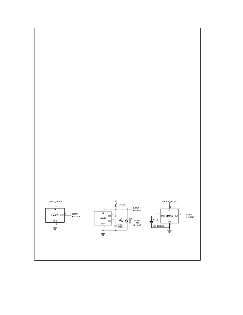
Typical Applications
Series Reference
TL/H/9110–2
Shunt Reference with Optional Trim
TL/H/9110–3
Series Reference with
Optional Filter
for Reduced Noise
TL/H/9110–4
NOTE:
Pin numbers for H, M or N packages.
5
相關PDF資料 |
PDF描述 |
|---|---|
| LM369BN | Precision Voltage Reference |
| LM369CN | Precision Voltage Reference |
| LM369H | Precision Voltage Reference |
| LM369DRC | Precision Voltage Reference |
| LM369DN | Precision Voltage Reference |
相關代理商/技術參數 |
參數描述 |
|---|---|
| LM369BN | 制造商:NSC 制造商全稱:National Semiconductor 功能描述:Precision Voltage Reference |
| LM369CN | 制造商:NSC 制造商全稱:National Semiconductor 功能描述:Precision Voltage Reference |
| LM369DM | 制造商:NSC 制造商全稱:National Semiconductor 功能描述:Precision Voltage Reference |
| LM369DMX | 制造商:NSC 制造商全稱:National Semiconductor 功能描述:Precision Voltage Reference |
| LM369DN | 制造商:Texas Instruments 功能描述: |
發(fā)布緊急采購,3分鐘左右您將得到回復。