- 您現(xiàn)在的位置:買賣IC網(wǎng) > PDF目錄358737 > LA76070 (Sanyo Electric Co.,Ltd.) NTSC Color Television IC PDF資料下載
參數(shù)資料
| 型號: | LA76070 |
| 廠商: | Sanyo Electric Co.,Ltd. |
| 英文描述: | NTSC Color Television IC |
| 中文描述: | NTSC制式彩色電視芯片 |
| 文件頁數(shù): | 20/27頁 |
| 文件大?。?/td> | 308K |
| 代理商: | LA76070 |
第1頁第2頁第3頁第4頁第5頁第6頁第7頁第8頁第9頁第10頁第11頁第12頁第13頁第14頁第15頁第16頁第17頁第18頁第19頁當(dāng)前第20頁第21頁第22頁第23頁第24頁第25頁第26頁第27頁
No. 5844-20/27
LA76070
Parameter
Symbol
Measurement
point
Input signal
Measurement procedure
Bus conditions and
input signals
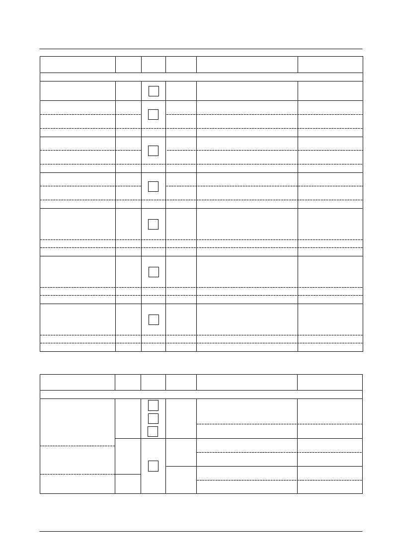
[OSD Block]
L–0
O–2
Apply a voltage to pin 36 and determine the pin
36 voltage when the output signal switches to
the OSD signal
OSD fast switch threshold
FS
TH
Pin 35: Apply O-2
Red RGB output level
R
OSDH
L–50
Measure the output signal 50 IRE amplitude
(CNTCR V p-p)
L–0
O–2
Measure the OSD output amplitude
(OSDHR V p-p)
Calculate R
OSDH
as 50
×
(OSDHR/CNTCR)
Measure the output signal 50 IRE amplitude
(CNTCG V p-p)
Pin 36: 2.0 V
Pin 33: Apply O-2
Green RGB output level
G
OSDH
L–50
L–0
O–2
Measure the OSD output amplitude
(OSDHG V p-p)
Calculate G
OSDH
as 50
×
(OSDHG/CNTCG)
Measure the output signal 50 IRE amplitude
(CNTCB V p-p)
Pin 36: 2.0 V
Pin 34: Apply O-2
Blue RGB output level
B
OSDH
L–50
L–0
O–2
Measure the OSD output amplitude
(OSDHB V p-p)
Calculate B
OSDH
as 50
×
(OSDHB/CNTCB)
Measure the amplitude of points A (the 0.35 V
section in the input signal O-1) and B (the 0.7 V
section in the input signal O-1) in the output
signal and record those values as RGBLR and
RGBHR V p-p, respectively
Pin 36: 2.0 V
Pin 35: Apply O-2
L–0
O–1
Pin 36: 2.0 V
Pin 33: Apply O-1
Analog OSD R output level
Gain matching
R
RGB
LR
RGB
Calculate R
RGB
as RGBLR/CNTCR
Calculate LR
RGB
as 100
×
(RGBLR/RGBHR)
Measure the amplitude of points A (the 0.35 V
section in the input signal O-1) and B (the 0.7 V
section in the input signal O-1) in the output
signal and record those values as RGBLG and
RGBHG V p-p, respectively
Linearity
L–0
O–1
Pin 36: 2.0 V
Pin 34: Apply O-1
Analog OSD G output level
Gain matching
G
RGB
LG
RGB
Calculate G
RGB
as RGBLG/CNTCG
Calculate LG
RGB
as 100
×
(RGBLG/RGBHG)
Measure the amplitude of points A (the 0.35 V
section in the input signal O-1) and B (the 0.7 V
section in the input signal O-1) in the output
signal and record those values as RGBLB and
RGBHB V p-p, respectively
Linearity
L–0
O–1
Pin 36: 2.0 V
Pin 35: Apply O-1
Analog OSD B output level
Gain matching
B
RGB
LB
RGB
Calculate B
RGB
as RGBLB/CNTCB
Calculate LB
RGB
as 100
×
(RGBLB/RGBHB)
Linearity
Parameter
Symbol
Measurement
point
Input signal
Measurement procedure
Bus conditions and
input signals
[RGB Output Block] (Cutoff and Drive Blocks)
Measure the output signal 0 IRE DC levels for
the R output (28), G output (29), and B output
(30). Record these values as BRTPCR,
BRTPCG, and BRTPCB V, respectively.
Contrast max
1111111
BRT63
L–0
Brightness control (normal)
Calculate BRT63 as
(BRTPCR + BRTPCG + BRTPCB)/3
(max)
BRT127
Measure the output signal 0 IRE DC levels for
the B output (30). Record this value as BRTPHB.
1111111
Brightness max
Calculate BRT127 as
50
×
(BRTPHB
–
BRTPCB)
/CNTHB
Measure the output signal 0 IRE DC levels for
the B output (30). Record this value as BRTPLB.
0000000
(min)
BRT0
Brightness min
Calculate BRT0 as
50
×
(BRTPLB – BRTPCB)/CNTHB
30
28
29
30
28
29
30
30
29
28
30
相關(guān)PDF資料 |
PDF描述 |
|---|---|
| LA76075 | NTSC Color Television Sets |
| LA7615 | Single-Chip NTSC Color TV IC |
| LA7620 | Color TV Video, Chroma, Deflection Circuit |
| LA7625 | Video, Chroma and Deflection Circuit for Color Television Sets |
| LA7629 | Color TV/Video,Chroma,Deflection Circuit |
相關(guān)代理商/技術(shù)參數(shù) |
參數(shù)描述 |
|---|---|
| LA76075 | 制造商:SANYO 制造商全稱:Sanyo Semicon Device 功能描述:NTSC Color Television Sets |
| LA7612A | 制造商:SANYO Semiconductor Co Ltd 功能描述: |
| LA7615 | 制造商:SANYO 制造商全稱:Sanyo Semicon Device 功能描述:Single-Chip NTSC Color TV IC |
| LA7620 | 制造商:SANYO 制造商全稱:Sanyo Semicon Device 功能描述:Color TV Video, Chroma, Deflection Circuit |
| LA7621 | 制造商:Panasonic Industrial Company 功能描述:IC |
發(fā)布緊急采購,3分鐘左右您將得到回復(fù)。