- 您現(xiàn)在的位置:買賣IC網(wǎng) > PDF目錄384585 > L6726ATR (意法半導(dǎo)體) Single phase PWM controller PDF資料下載
參數(shù)資料
| 型號: | L6726ATR |
| 廠商: | 意法半導(dǎo)體 |
| 英文描述: | Single phase PWM controller |
| 中文描述: | 單相PWM控制器 |
| 文件頁數(shù): | 5/24頁 |
| 文件大?。?/td> | 399K |
| 代理商: | L6726ATR |
L6726A
Pins description and connection diagrams
5/24
2
Pins description and connection diagrams
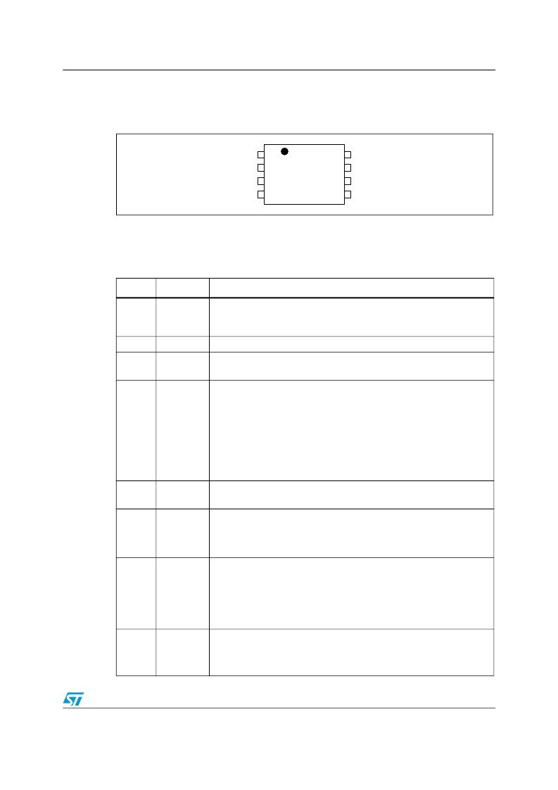
Figure 3.
Pins connection (Top View)
2.1
Pin descriptions
Table 1. Pins descriptions
1
2
3
4
VCC
FB
COMP / DIS
PHASE
LGATE / OC
GND
UGATE
BOOT
5
6
7
8
L6726A
Pin #
Name
Function
1
BOOT
HS Driver Supply.
Connect through a capacitor (100nF) to the floating node (LS-Drain) pin
and provide necessary bootstrap diode from VCC.
2
UGATE
HS Driver Output. Connect to HS mosfet gate.
3
GND
All internal references, logic and drivers are connected to this pin.
Connect to the PCB ground plane.
4
LGATE / OC
LGATE
. LS Driver Output. Connect to LS mosfet gate.
OC
. Over Current threshold set. During a short period of time following
VCC rising over UVLO threshold, a 10
μ
A current is sourced from this pin.
Connect to GND with an R
OCSET
resistor greater than 5k
to program OC
Threshold. The resulting voltage at this pin is sampled and held internally
as the OC set point. Maximum programmable OC threshold is 0.55V. A
voltage greater than 0.75V (max) activates an internal clamp and causes
OC threshold to be set at 375mV. R
OCSET
not connected sets the 375mV
default threshold.
5
VCC
Device and LS Driver power supply.
Operative range from 4.1V to 13.2V. Filter with at least 1
μ
F MLCC to GND.
6
FB
Error Amplifier Inverting Input.
Connect with a resistor R
FB
to the output regulated voltage. Additional
resistor R
OS
to GND may be used to regulate voltages higher than the
reference.
7
COMP / DIS
COMP.
Error Amplifier Output. Connect with an R
F
- C
F
// C
P
to GND to
compensate the device control loop in conjunction to the FB pin.
During the Soft-Start phase, a 10
μ
A current is sourced from this pin so the
compensation capacitors also act to program the SS time.
DIS.
The device can be disabled by pulling this pin lower than 0.4V (min).
Setting free the pin, the device enables again.
8
PHASE
HS Driver return path, current-reading and adaptive-dead-time monitor.
Connect to the LS drain to sense R
dsON
drop to measure the output
current. This pin is also used by the adaptive-dead-time control circuitry to
monitor when HS mosfet is OFF.
相關(guān)PDF資料 |
PDF描述 |
|---|---|
| L6727 | Single phase PWM controller |
| L6727TR | Single phase PWM controller |
| L6730CQ | Adjustable step-down controller with synchronous rectification |
| L6730C | Adjustable step-down controller with synchronous rectification |
| L6730CQTR | Adjustable step-down controller with synchronous rectification |
相關(guān)代理商/技術(shù)參數(shù) |
參數(shù)描述 |
|---|---|
| L6726-D18-T | 制造商:UTC-IC 制造商全稱:UTC-IC 功能描述:UNIVERSAL SPEECH CIRCUIT |
| L6726G-D18-T | 制造商:UTC-IC 制造商全稱:UTC-IC 功能描述:UNIVERSAL SPEECH CIRCUIT |
| L6726G-S18-R | 制造商:UTC-IC 制造商全稱:UTC-IC 功能描述:UNIVERSAL SPEECH CIRCUIT |
| L6726G-S18-T | 制造商:UTC-IC 制造商全稱:UTC-IC 功能描述:UNIVERSAL SPEECH CIRCUIT |
| L6726L-D18-T | 制造商:UTC-IC 制造商全稱:UTC-IC 功能描述:UNIVERSAL SPEECH CIRCUIT |
發(fā)布緊急采購,3分鐘左右您將得到回復(fù)。